Meanwell LDD driver: for those who want to dim to 0 using Arduino

Another suggestion... test the current running from your LED to the Vout- of the one that is showing a dropped voltage, maybe all of the current is going out through one driver? Since they are wired in parallel, this little electrons might not know where to go :)

LDD#2 might be 27.3V out+ and 27.3V out- but the difference between out+#2 and out-#1 is still in the ballpark of physics to get you 1300mA from two drivers.

That's the problem- All of the current is returning through the Vout- connection at LDD#1 and not LDD#2. I connected my amp meter between Vcc and + terminal of the power supply and measured 1.35 amps. I then removed the Vout- connection from LDD#2 expecting the current to drop. It did not, and remained at 1.35 amps. The only connection available for the current to travel back to the LDD's was through the Vout- @ LDD#1. This leads me to believe that the second LDD influences the current limiting of the first, causing it to carry double of the load.
I'm going to re-run the experiment again with all 4 isolation diodes in place and test to see if the current is actually shared between the two LDD's or not. It appeared to be shared on the first go around of testing but I want to make sure for Tomservo's sake.
 
Last edited:
Ugh, you better have a comfortable seat cuz you're gonna be waiting a while. In my experience, shipping via "the slow boat" takes between 2 and 4 weeks to arrive. That's why it's best to just double down on the $$ and go with expedited shipping. LOL

Yikes. And now it's Chinese New Year, so they'll likely sit in the post for a while before leaving the country. My shipping info said Hong Kong post, but the billing on my account said Guangdong, China. Maybe the company or payment processor is based in mainland China while the fab is in Hong Kong?
 
Anyone order using the cheaper shipping at itead? How long did it take for the boards to arrive? I got the email 1/31 that it was shipped, but so far the tracking still says it's still being processed by HK post to leave Hong Kong. Hmm.

It's coming up to Chinese New Year too = extra delay ++.

Peter
 
That's the problem- All of the current is returning through the Vout- connection at LDD#1 and not LDD#2. I connected my amp meter between Vcc and + terminal of the power supply and measured 1.35 amps. I then removed the Vout- connection from LDD#2 expecting the current to drop. It did not, and remained at 1.35 amps. The only connection available for the current to travel back to the LDD's was through the Vout- @ LDD#1. This leads me to believe that the second LDD influences the current limiting of the first, causing it to carry double of the load.
I'm going to re-run the experiment again with all 4 isolation diodes in place and test to see if the current is actually shared between the two LDD's or not. It appeared to be shared on the first go around of testing but I want to make sure for Tomservo's sake.

Ahh I see, the way your first post went you were talking about laws of physics being violated, as if you got current from nothing. :)

So if you measure the current from the Vout+ of each driver to the LED you're probably getting the same current from each, it just is deciding to return through one driver and not both. Wonder if that is a design function or just the way things work, I'm sure from an electrical standpoint both drivers are "seeing" the same exact circuit. It's just odd that one driver is syncing to the Vout- of the other driver rather than it's own Vout-.
 
That's the problem- All of the current is returning through the Vout- connection at LDD#1 and not LDD#2. I connected my amp meter between Vcc and + terminal of the power supply and measured 1.35 amps. I then removed the Vout- connection from LDD#2 expecting the current to drop. It did not, and remained at 1.35 amps. The only connection available for the current to travel back to the LDD's was through the Vout- @ LDD#1. This leads me to believe that the second LDD influences the current limiting of the first, causing it to carry double of the load.
I'm going to re-run the experiment again with all 4 isolation diodes in place and test to see if the current is actually shared between the two LDD's or not. It appeared to be shared on the first go around of testing but I want to make sure for Tomservo's sake.

That was kind of my fear, if run like this LDD#1 may burn out at some point. since you noticed it getting pretty hot this might be a problem If you measure current from each LDD's Vout+ are you getting equal ~650 or only 1300 output on LDD#1? If you already checked that sorry, I may have missed it.

Based on the following I think diodes on both Vout + and - may be required:

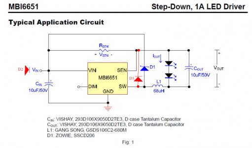
I just took a closser look at the Sure drivers that i have and they have two diodes parreleled on the Vout- side presumable to handle more current than the diodes rated 1 amp? Vin + goes straight to the Vout+ thru a diode. these run on a mbi6651 chip which is only rated at 1 amp output but I guess maybe the Vout- side of the chip can handle more current? seems to create a "loop" of sorts back to Vin +(understanding that part goes way beyond my hobby eletcronics stills.....) here is a schematic I edited to reflect this driver, I added the two diodes in red, D2 & D3. Hope this helps the cause.
 

Attachments

  • Sure Electronics Driver Schematic_sm.jpg
    Sure Electronics Driver Schematic_sm.jpg
    43.8 KB · Views: 15
Can somebody give me a link for the 24 pin ic socket adapters. I ordered some and they are too narrow for my ldd-h drivers. I want to make sure I get the right ones this time.

Page 2 of the specsheet for the LDD-H gives the pin width spacing at 15.24mm or 0.6in with 2.54mm spacing (0.1in) between pins and a total of 24 pins. I believe this is the standard for a "Wide" IC holder.

Here's the link to the specsheet:

http://www.meanwell.com/search/LDD-HW/LDD-H-spec.pdf

and here's a link to a Mouser part, which is pretty expensive at 1.68 each compared to ones for about 0.50 each from China on ebay:

http://www.mouser.com/Search/Refine.aspx?Keyword=575-11044324

O2Surplus or rrasco can confirm better, but I think that socket part will accept the LDD-H perfectly. I'm still waiting for mine to arrive from china, so I can't confirm.
 
I finally found some time to start soldering the boards and 120+ leds to my fixture. I'm hoping to have it fully done by next weekend. Once it is, I'll show some pics of the drivers in action.
 
Quick question of those with LDDs (and can read current handy)... what's the current draw from the power supply to the LDD Vin+ (should be same as Vin-.. but whatever). The data sheet states 900mA (at full load) on the 1000mA version, and I'm having a friendly discussion with someone about what the power supply requirements are needed.

My thought is that it needs 900mA, so if I have 10 LDD-1000h drivers, I'd need the PS to handle 9amps

He says having more voltage necessary (54V PS with 30V needed for LEDs) will convert voltage into current at the LDD, in this example needing only about 5amps for the same 10 drivers.

Now this got me second guessing how much of current requirement I'll need from my power supply (which will be 48V)
 
As far as what my friend who plays with electronics says, that is correct. So long as voltage is excess and PSU output is more than needed, it should work. The excess voltage has to go somewhere.
 
Last edited:
Quick question of those with LDDs (and can read current handy)... what's the current draw from the power supply to the LDD Vin+ (should be same as Vin-.. but whatever). The data sheet states 900mA (at full load) on the 1000mA version, and I'm having a friendly discussion with someone about what the power supply requirements are needed.

My thought is that it needs 900mA, so if I have 10 LDD-1000h drivers, I'd need the PS to handle 9amps

He says having more voltage necessary (54V PS with 30V needed for LEDs) will convert voltage into current at the LDD, in this example needing only about 5amps for the same 10 drivers.

Now this got me second guessing how much of current requirement I'll need from my power supply (which will be 48V)

Ugh- When I measured the current consumption of two LDD -700H running in tandem, I measured 1.35 amps. Since the LDD is a constant current device and not a transformer, I'd error on the side of caution and use a power supply with a current rating that exceeds your required current needs by at least 20%.
 
Ugh- When I measured the current consumption of two LDD -700H running in tandem, I measured 1.35 amps. Since the LDD is a constant current device and not a transformer, I'd error on the side of caution and use a power supply with a current rating that exceeds your required current needs by at least 20%.

see, there must be some magic going on inside those drivers since it pulls less current than it puts out... at least according to the spec sheets. A 1000H pulls 900mA and puts out 1000mA.
 
Quick question of those with LDDs (and can read current handy)... what's the current draw from the power supply to the LDD Vin+ (should be same as Vin-.. but whatever). The data sheet states 900mA (at full load) on the 1000mA version, and I'm having a friendly discussion with someone about what the power supply requirements are needed.

My thought is that it needs 900mA, so if I have 10 LDD-1000h drivers, I'd need the PS to handle 9amps

He says having more voltage necessary (54V PS with 30V needed for LEDs) will convert voltage into current at the LDD, in this example needing only about 5amps for the same 10 drivers.

Now this got me second guessing how much of current requirement I'll need from my power supply (which will be 48V)

Ugh- When I measured the current consumption of two LDD -700H running in tandem, I measured 1.35 amps. Since the LDD is a constant current device and not a transformer, I'd error on the side of caution and use a power supply with a current rating that exceeds your required current needs by at least 20%.

see, there must be some magic going on inside those drivers since it pulls less current than it puts out... at least according to the spec sheets. A 1000H pulls 900mA and puts out 1000mA.

Response from MeanWell.
Hi Jared,
Yes, if you have a 10V/500mA power supply, the LDD-1000H can turn your
3V LED on.
 
Page 2 of the specsheet for the LDD-H gives the pin width spacing at 15.24mm or 0.6in with 2.54mm spacing (0.1in) between pins and a total of 24 pins. I believe this is the standard for a "Wide" IC holder.

Here's the link to the specsheet:

http://www.meanwell.com/search/LDD-HW/LDD-H-spec.pdf

and here's a link to a Mouser part, which is pretty expensive at 1.68 each compared to ones for about 0.50 each from China on ebay:

http://www.mouser.com/Search/Refine.aspx?Keyword=575-11044324

O2Surplus or rrasco can confirm better, but I think that socket part will accept the LDD-H perfectly. I'm still waiting for mine to arrive from china, so I can't confirm.

Yeah, do a search on ebay for wide 24 pin ic socket and you should get the right ones. Here are mine soldered to the board.

35bxmww.jpg
 
O2Surplus: Thanks for checking these out thoroughly for me, I really appreciate your help. It sounds like the condition you observed with the vout- (2) disconnected that the current is measured on the positive side based on floating the negative - but since the (1) can't sense the current of the (2) in this condition, it ends up carrying the extra current without sensing it. If you look at a diagram from zachts with a likely similar arrangement, the current all goes through R-SEN, but if the current being measured is only half (because the R-SEN is equal in both LDDs), then the current would actually be doubled. I think the diodes probably need to be on both sides in this case? But I'm very tired and not thinking particularly well right now.
 
Yeah, do a search on ebay for wide 24 pin ic socket and you should get the right ones. Here are mine soldered to the board.

35bxmww.jpg

i made a similar schematic in a protoboard ,.

and i have some questions.
1)is it wise to attach a 10 Ohms resistor into PWM pin of LDD to PWM pin of arduino?? (to protect arduino)
2)When the arduino is not powered i want the led to be at 0 level (closed by default) how can i do this?
3)is there any code example for day cycles of this 5 LDD arduino driver?
Thanks..
 
Last edited:
To follow-up my previous measurements on the current draw of the LDD dimming circuit I enlisted the assistance from someone who knows more about electronics then me. It turns out my measurements were sort of correct, I just had a decimal point in the wrong place.

So, the actual measurements are:

100% duty cycle - 7.7uA
0% duty cycle - 53uA

Please note that these are micro amps rather than milli amps. So, in effect, we are never going to get close to exceeding the current limitations of the Arduino pins or board.

We also checked out the dimming control on an oscilloscope - there is a very sharp edge on the cycle which apparently suggests a FET or something similar. It was also suggested that, because of the way this is working, there is no dumping of excess voltage which explains why a 48v supply with one led does not result in the LDD getting hot.
 
Could someone tell me if this would work:

one PS (24V 9A)

2x strings of 6 Cree XML CW at 1A about 3,3V
4x strings of 6 Cree XT-E RB at 1A about 3,3V
6 LDD-100H

one PS (24V 9A)
2x strings of 2 Cree XP-E Green at 0,7A 3,3V
2x strings of 2 Cree XP-E Blue at 0,7A 3,3V
2x strings of 2 Cree XP-E Red at 0,7A 2,3V
2x strings of 5 UV led 0,7A and about 3,5V
8 LDD-700H

Can I use some resistors to be able to handle the V on the second setup?

Looks like it would work, to me.

I don't think you should put resistors on there. You'd be burning a pile of power in the resistor trying to get the voltage drop up to 24V. I assume you're doing it to try to get up to closer to 24V? It's not necessary because the driver has components that already do what you're trying to do much more efficiently.

The spec sheet for the LDD I posted above shows the efficiency with different input voltages for different numbers of chips, and it's not terrible even if you're only putting 7 volts of LEDs on a 24V power supply. But why not do 1 String of 4 green and 1 string of 4 blue and 1 string of 4 red? Fewer LDD-700H to buy, and they'd run more efficiently.

Edit: here's link to spec sheet. Go to graphs on the last page and look at the one for 24V input. http://www.meanwell.com/search/LDD-HW/LDD-H-spec.pdf
 
Last edited:
Back
Top