Meanwell LDD driver: for those who want to dim to 0 using Arduino

Got my (20) 1000's from PowerGateLLC today!:celeb1:

Rub it in.


They were out when i ordered. They have a few wired ones coming. I am not sure how I am going to place them in the line up but I ordered two wired ones just to have the 1000 ma option to power two strings. I will put 4 of the 1000H LDDs for the April order.
 
@O2SurPlus; electronics for dummies question 2 (ghehe)

To get it clear, i would then supply 5V to one end of the 1kOhm resistor (this is the pullup?), and connect the other end to one of the 4 driver lines, as shown in the picture right? What would i do with the V- of the 5V power supply?

Can someone point me in a right direction on the choice of drivers vs amount of leds? If i would like to use CREE XP-G R5 5W leds and i would like to run them at 700mA (LDD-700H);
The Forward voltage (@ 700 mA) for the CREE XP-G R5 5W is 3.2v; this would mean i could connect (in case of an 48V power supply) 48/3.2=15 leds if i am correct.

So does this mean that:
- i would need a power supply capable of giving (15*3.2) 48V and (15*0.7) 10.5A
(or)
- i would need a power supply capable of giving 3.2V and (15*0.7) 10.5A

So confused....
 
Last edited:
You're connecting them in series, so you need 48v and 700mA to run the 15 emitters. You actually need a few volts of headroom to run the drivers in addition to LEDs, but most 48v power supplies seem to be adjustable by a few volts, so you should be fine turning the power supply up to 52v or something.
 
You're connecting them in series, so you need 48v and 700mA to run the 15 emitters. You actually need a few volts of headroom to run the drivers in addition to LEDs, but most 48v power supplies seem to be adjustable by a few volts, so you should be fine turning the power supply up to 52v or something.

Ok, so if i understand it right:
- if i connect them in series; i'd need a 48V 700mA
- if i connect them in parallel; i'd need a 4V 11A power supply?

What is safer with aquariums? More V or more A?

And is it somehow possible to shut off the Vin when the PWM signal is 0? According to the datasheet this must be possible...
 
No offense, but this is pretty basic electrical stuff. First week in a basic electronics class. Are you sure you are ready to do a DIY fixture since you seem not to know it?

If you ran them in parallel you'd need a driver for every individual led. No one would run them that way. Also, this is an oversimplification, but voltage is safer than current.
 
Giles how many total LEDs are you wanting to run? The cost of the drivers is relatively low I would recommend not putting 15 on one string its never wise to push the limitations. So for example if you are only wanting 15-16 leds you could do two strings of 8 on a 36v 2A power supply. The voltage the power supply is rated for will be sent to each string but the current will be split between the strings. You should always give yourself a little headroom with the current rating on the power supply. If you let me know how many LEDs you are wanting to run I will try and help you.

Current is the part of electricity that is the most likely to kill you. If you get hit with a high voltage it will more than likely knock you away from the power source if you get hit with a high current it usually locks you onto whatever is electrocuting you and you cannot let go. Current as low as 10ma can kill you so just be careful :)
 
Well, i've posted my same question on a Dutch computer forum with an electronics part on it. Basically i think i might have a workable solution for the LedControl4Passive.

All there is left is a schema for a 220v relay which turns off at 0V and turns on at anything above 0V.
If this is in place then i think i'll fire up Eagle for the first time in my life and try to get it all on 1 schematic.
Basically what i want is to switch the power supply for the drivers based on the PWM signal.
 
Last edited:
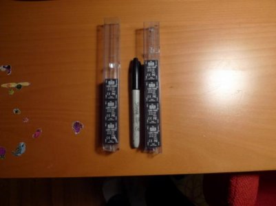
Got my LDD's today from Mouser! I hadn't fully appreciated just how small these things would be. Put a normal sized Sharpie next to them for comparison. Hard to believe I can put 48V and 1A through them. No boards yet though.

P1020245.jpg
 
Just so we are clear, when I'm hooking this up (Since I'm new to this)

I've got my *Duino board on one side, and my board of LDD's on the other.

Obviously from PWM -> PWM that's an easy hook up.

I now need to tie a ground, or it doesn't work. I"m going from the GND pin of my *duino to the -V of the powersupply which is tied to the -V in of the drivers, correct?

Thanks!
 
Sweet! I was hoping this would isolate them sufficiently. I was just thinking that if the voltage couldn't get from one to the other, it should work.
That's weird, but it's probably better that they work together than otherwise. Did you by chance try it with diodes only on the + or - side?

Even if I can't modify the board sufficiently to stick some SMD diodes on, I bet I can finagle something. The white channels can just be single, 1A drivers since the white is overpowering anyways, and the actinic shouldn't really be run past 1A, so only two channels really need to be dual driver. Going to update the schematic soon anyways so it's done if I ever need to make more boards.

Thanks for trying!

Hi Tom, are you saying that your going to update your gerber files so you can double up the LDD's ?---Rick
 
Rick, that is my intention, I did want to try some things once I have some LDDs to play with, like using only one diode per LDD to isolate, so I have not actually updated the drawing yet. It should only take a few minutes to do it, though, if you want the files with the diodes I can probably get around to it today.
 
Rick, that is my intention, I did want to try some things once I have some LDDs to play with, like using only one diode per LDD to isolate, so I have not actually updated the drawing yet. It should only take a few minutes to do it, though, if you want the files with the diodes I can probably get around to it today.


Tomservo- here's link to a schottky diode that would work well for your application. It's an SMD device and should be small enough to squeeze into your Pcb design. It's electrical specs are also inline with using it with an LDD-1000h http://www.digikey.com/product-detail/en/PMEG6010CEH,115/568-4104-1-ND/1589917
 
Back
Top