Meanwell LDD driver: for those who want to dim to 0 using Arduino

sorry so, not on topic but, nice avatar! a refreshing change from the reef related norm :) and I just so happen to be listening to them right now....

:beer:

Yes, not on topic, but.....I saw them at Rams Head Live a couple of years ago and they freaking tore it up, awesome show!!! Rams Head is such a small venue, for 3 days afterward all I could hear was a high pitch ringing...EeeeeeEEEeeeeeeeeeeeeeeeeeeeeeeeeeeee :thumbsup:
 
Don't the MakersDrivers have LDDs in them?

Apparently those are analog and not PWM so you cant use with arduino (jarduino, typhon etc) Unless you know how to remove the conversion. I sure dont.

Looks like its set up to work with DIM4 and their new makers controller which isnt out yet. Doesnt look like theyre giving any details on it yet though.
 
If anyone is still looking for a few ldd's, onlinecomponents.com has around 80 of the 1000h's and a few 600h's for around $7 a piece. Not cheap, but better than mouser.
 

Attachments

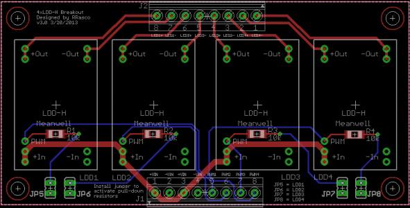
  • LDD-Hx4 Breakout v3.0.png
    LDD-Hx4 Breakout v3.0.png
    20.2 KB · Views: 8
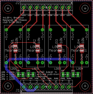
  • LDD-Lx4 Breakout v3.0.png
    LDD-Lx4 Breakout v3.0.png
    11.9 KB · Views: 11
Yes, 2 LDD-1000H but they're $62 a pop..and only good for 14 led's per LDD.

Yeah, but they have power integrated into them, and a dimming control (manual) so it's too horrible if all you need is two channels. Most likely they wanted it to fit on their heatsink, and that isn't going to happen with a 300watt power supply, and 8 LDDs :)
 
I was asked via PM to add, the amazing design feature of sir O2, jumpers to my boards. So, ask and ye shall receive. I'm pretty sure I did this right. LOL.


LOL You got it right.

:headwally: NOW I'm being asked to work in a 10 analog/ 5V PWM convertor to my PcB design! Care to join me?LOL :lmao:
 
LOL You got it right.

:headwally: NOW I'm being asked to work in a 10 analog/ 5V PWM convertor to my PcB design! Care to join me?LOL :lmao:

You mean they want Analog -> PWM converter? I know how to go from PWM to Analog but not the other way.
 
LOL You got it right.

:headwally: NOW I'm being asked to work in a 10 analog/ 5V PWM convertor to my PcB design! Care to join me?LOL :lmao:

That would be great! Glad I haven't ordered my boards yet. Can't wait to see what you come up with.

Thanks for helping us with these designs!
 
Yeah, but they have power integrated into them, and a dimming control (manual) so it's too horrible if all you need is two channels. Most likely they wanted it to fit on their heatsink, and that isn't going to happen with a 300watt power supply, and 8 LDDs :)

I didnt realize it had integrated power. Thats not a bad deal. Still I think I'd prefer PWM since it seems more versatile, you can use it in arduino.

So whats the benefit of a 10 analog/ 5V PWM convertor? That the board can be used in either analog or pwm mode?
 
You mean they want Analog -> PWM converter? I know how to go from PWM to Analog but not the other way.

Yep- 10V analog to 5V PWM. I've already got the design worked out on a separate PcB using an Atmega 328-au, but I'm waiting for the software side to come together. Evidently, there's a few people out there that want to control their LDD's from an APEX or other similar controller. I probably go ahead and squeeze it all into one PcB OR just incorporate plug in connections for an Arduino pro-mini.
 
O2Surplus,

Asked this of Chicken a couple of page back, but you probably know.

I'm getting my 5V to power a Steves AQI which generates 5V PWM from 0-10V input from a 48V DC/DC converter. I assume the ground going in to the AQI needs to be the same ground that the LDD sees on the power input and ground plane of the boards you made so that the PWM signal has a consistent reference.

I would end up tying the ground for the 48V stuff to the ground for the 5V AQI.

It would be the output ground of the Meanwell 48V supply, the input of my DC/DC converter (which is the same as the Meanwell 48V output), the input of my LDDs (which is also the same as the Meanwell 48V output), the output of the DC/DC converter, and the input of the Steve's AQI (which is the same as the output of the DC/DC converter) all together.

Does it seem like that should work?

Tie all your grounds together and everything should work just fine. Make sure that your SteveLed convertor is getting it's power from the DC/DC convertor, as 48V is too high for the 5V reg on the StevesLed convertor to handle. I'm working on a solution for my version that will eliminate the need for the DC/DC convertor between the 48V supply and the 5v reg @ the 10V/5VPWM circuitry.
 
OK, thanks.

I thought that was OK because I asked my smart officemate if it should work and he went in to how AC/DC power supplies are built and how the grounds all float and how you can actually tie together the + or - of them, and it doesn't matter. Just don't tie both together at the same time. 8)

I also found out that the guys downstairs have tiny little Meanwell 120VAC to 5VDC power supplies. Might have to liberate one of those from it's home in the drawer.
 
A semi unrelated question. I can't seem to find a chart I understand but what size wire are you guys using? I've got a couple strings theoretically can run 3000 mA (XM-L's), the rest are 1500Ma and under. Is 20 awg ok for the 3000mA? Should I be running smaller (22 wag) for the XT-E's?
 
LDDPcbs008_zpsdef8f686.jpg


All in all it works great. I found a few instances where components interfere with each other, "fit wise", but they're no big deal to work around. I'm going to revise the design of the two Pcb's a bit to correct the problems, and post them on this forum for everybody who may want to build one.

Are the latest iterations of the 4ldd board going to fit into the typhon (or any arduino) the same way as this pic? Keeping it all in one compact unit was a big benefit.
 
Yeah, but they have power integrated into them, and a dimming control (manual) so it's too horrible if all you need is two channels. Most likely they wanted it to fit on their heatsink, and that isn't going to happen with a 300watt power supply, and 8 LDDs :)

Even for the nano guys with small fixtures, one would still need to purchase a minimum of 2 of these (@$62 each). I don't think there is anyone these days that is only running 2 colors in their diy setups. Most have at least 4 colors on separate channels and sometimes more. You would also still need to purchase a separate 48V DC power supply for them (~ $45 each). I agree with risk1994 in that I think they are intended to be used with a controller they plan on releasing soon. But until that happens and we can see what the capabilities are, for me anyway, this thing just doesn't make sense money wise. For my planned setup, I would need 5 MakersDrivers totaling $310. On the other hand, a total of 10 LDD's, 4-500mA and 6-1A will only run me $54.40. That's a huge difference. It brought my total calculated price tag including heatsinks, MakersDrivers, LED's and power supply from $1127.43 down to $871.83 by switching to the LDD/Arduino combo.
 
Back
Top