You are using an out of date browser. It may not display this or other websites correctly.
You should upgrade or use an alternative browser.
You should upgrade or use an alternative browser.
Meanwell LDD driver: for those who want to dim to 0 using Arduino
- Thread starter pwreef
- Start date
As soon as I finish it up i'll post the files for those who want to try and use the 16x controller. Weather here is in 70's cichlidtx, but has been hotter...lol.
Thanks, I'm using the Storm controller at this time. I was interested in the LLD 6up board only at this time. I may give the 16x controller a try as well.
Thank you sir, much appreciated. Happy 4th and also appreciate what you do/did for all of us.
You're most welcome. It's a job like any other to me and I enjoy it. Cheers :beer:
Off-topic but LDD-H Related...
Off-topic but LDD-H Related...
O2Surplus,
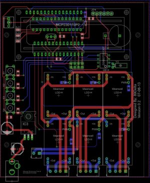
I took a look at all the Enclosures that Mouser has to offer and I chose to go with the CM5-200 they have as the data sheet had the PCB dimensions. With the extra room I threw on an atmega chip and an MCP23017 for the LCD. I was thinking about adding a breakout pinheader to use the Atlas Scientific Muxer with pH, ORP and salinity breakout boards. The PCB's for this would be 10x15 from Seeed (10x12.9 to be exact to fit the enclosure). But if I were to go the full 10x15 i'd have room to add the Atlas boards but no enclosure. There are 6-channels though, one for each of the 6 LDD-H drivers. I'm sure if I moved some things around I could probably add a SMD BT or WiFi module to the underside of the PCB......Ideas/comments please.
Off-topic but LDD-H Related...
O2Surplus,
I took a look at all the Enclosures that Mouser has to offer and I chose to go with the CM5-200 they have as the data sheet had the PCB dimensions. With the extra room I threw on an atmega chip and an MCP23017 for the LCD. I was thinking about adding a breakout pinheader to use the Atlas Scientific Muxer with pH, ORP and salinity breakout boards. The PCB's for this would be 10x15 from Seeed (10x12.9 to be exact to fit the enclosure). But if I were to go the full 10x15 i'd have room to add the Atlas boards but no enclosure. There are 6-channels though, one for each of the 6 LDD-H drivers. I'm sure if I moved some things around I could probably add a SMD BT or WiFi module to the underside of the PCB......Ideas/comments please.
Attachments
O2Surplus,
......Ideas/comments please.
89Delta,
I know you asked O2Surplus however I have a couple thoughts that may help.
1) I would add pull-up resistors to your I2C SDA and SCL lines.
2) A bypass cap close to Vcc on the RTC would be a good idea.
3) Maybe make the two vias for power into the LDD's larger.
Cheers,
-BB
Did the first two after the posting and added 2 diodes for protection on both driver and controller circuits.
Good job.
You may also want to check the max current of the backlight for your LCD.
It looks like the MCP23017 can source 25mA max on any output pin and your LCD backlight may want a lot more.
The LCD's I have used normally draw 60-100+mA
I suggest a transistor.
Cheers,
-BB
Just when I think I have things figured out I stumble across things like thise thread and start wondering if I have a clue.
With regard to using the LDD-1000's on lower apmerage lights, (500 or 750 ma) I had planned on using the typical limiting resistors on the VCC input of the drivers to limit the current. Is there something I'm missing with that plan?
The other thing, I see a lot of mention of using these LDD-1000's with the XT-E royal blue and warm whites. But those leds are rated at 1500ma, but the LDD's are only rated for 1000ma. I presume that would mean that those LED's are only being driven at about 2/3's of their full potential?
Sorry if this has been discussed elsewhere, I missed it if it was.
Thanks
nemosworld
Active member
running xte's on 1 amp will make it more efficient, also unless you have a deep tank, you will not be running any xte at one amp with optics on it, you my friend will have dead coral unless you raise the fixture high.Just when I think I have things figured out I stumble across things like thise thread and start wondering if I have a clue.
With regard to using the LDD-1000's on lower apmerage lights, (500 or 750 ma) I had planned on using the typical limiting resistors on the VCC input of the drivers to limit the current. Is there something I'm missing with that plan?
The other thing, I see a lot of mention of using these LDD-1000's with the XT-E royal blue and warm whites. But those leds are rated at 1500ma, but the LDD's are only rated for 1000ma. I presume that would mean that those LED's are only being driven at about 2/3's of their full potential?
Sorry if this has been discussed elsewhere, I missed it if it was.
Thanks
i would not run any led rated for 500ma on a 1000H either, they make 350h's which would be a safer bet, they even have 500h as well.
now if you are determine to run 500ma leds on a 1000h then i suggest you run them in parallel.

Just when I think I have things figured out I stumble across things like thise thread and start wondering if I have a clue.
With regard to using the LDD-1000's on lower apmerage lights, (500 or 750 ma) I had planned on using the typical limiting resistors on the VCC input of the drivers to limit the current. Is there something I'm missing with that plan?
If you use PWM dimming there is no need for current limiting resistors. Current output is proportional to PWM duty cycle (+/-3%).
The other thing, I see a lot of mention of using these LDD-1000's with the XT-E royal blue and warm whites. But those leds are rated at 1500ma, but the LDD's are only rated for 1000ma. I presume that would mean that those LED's are only being driven at about 2/3's of their full potential?
Sorry if this has been discussed elsewhere, I missed it if it was.
Correct.
I guess many people including myself do not run XT-E's anywhere close to 1500mA.
I have not found a graph from Cree showing current / junction temperature over life expectancy but I can imagine that as current / junction temperature rises life expectancy falls in a non linear curve.
I may be wrong on both points?
-BB
Unless the LDDs have changed recently you cannot use a resistor to limit current. they run at their rated output current and can only be dimmed via PWM, otherwise they are just on full power. the multimeter may see a pwm dimmed led getting less current but that is an issue with how the meter works. the LED would still be getting the full 1000mA just in shorter pulses which make it appear less bright. So you would be overdriving any led not rated to handle at least 1000mA and drastically shorten its life span.If you use PWM dimming there is no need for current limiting resistors. Current output is proportional to PWM duty cycle (+/-3%).
Parallel is a good option as previously suggested, or just use lower rated LDDs would be better.
Yep, at their maximum rated current most LEDs will wear out much faster than the typical 50,000hr life span, it depends on how the rating your looking at is measured. In the case of lesser quality LEDs that may take the life down from years to just a few months.Correct.
I guess many people including myself do not run XT-E's anywhere close to 1500mA.
I have not found a graph from Cree showing current / junction temperature over life expectancy but I can imagine that as current / junction temperature rises life expectancy falls in a non linear curve.
-BB
many LEDs use a 25 degree Celsius junction temp to make their ratings. this temperature is not realistically achievable in real world applications. I saw on an XML data sheet a while back that they rated it at 3 amps and a junction temp of 25C, I think they were running it in a freezer for testing, LOL.
I think they were running it in a freezer for testing, LOL.
:lolspin: :lolspin: :lolspin:
Good question- Start here-http://imall.iteadstudio.com/
1.) select the 10 x 10cm size PcB option for this particular PcB.
2.) choose a thickness. I go for the thickest "free" option available.
3) Choose a surface finish- Go with what ever the "free" option is.( let somebody else pay to save the planet. Lol)
4. Choose a color, again going with "Green" is free. Other colors are going to cost add'l money.
5.) submit payment(make sure to pay for expedited shipping. YOU don't want to be THAT GUY who's still waiting a month later for his PcB's to ship. Do You?) and wait for the confirmation Email that lists your Order #.
6.) Rename the zip folder marked "GERBER FILES for Itead" to include your Order # and Email it to ITead.
7.) Sit back and wait. If everything goes according to plan, you should receive your PcB's in 10 - 14 days.
:beer:
Hi Sir, what does it means "*Open Source And Get 2 More Additional Boards"
Should click Yes or No, sorry for asking such a question.
Thanks for sharing your hard work with everyone of us. Like the Boards design.
heatdissipation
New member
The open source option is a way they distribute other people's boards. If you check yes they will send you two random boards. Might be something you could use, or it might not be. But you will get what you ordered no matter what
I have a question. I am trying to cut down on number of wires and was wondering if the Vout- can be shared or tied together as one.
No- the outputs can't be tied together. The LED outputs have to remain electrically isolated from each other for the LDD's to work properly.
Similar threads
- Replies
- 3
- Views
- 2K
- Replies
- 46
- Views
- 13K