So i've been reading this post for the past three days now and i've actually enjoyed it. With O2surplus and I having similar designs in an all-in-one controller/driver idea I thought i'd share what i've come up with on the LDD-H's. It is a 6up and the layout is the same a josh as far as driver placement. But i've added an ethernet jack with each driver being selectable to one of six channels as the controller i'm working on is using the I2C for the LCD as well as a relay unit I'd like to be able to use.
You are using an out of date browser. It may not display this or other websites correctly.
You should upgrade or use an alternative browser.
You should upgrade or use an alternative browser.
Meanwell LDD driver: for those who want to dim to 0 using Arduino
- Thread starter pwreef
- Start date
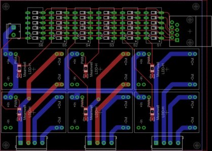
So i've been reading this post for the past three days now and i've actually enjoyed it. With O2surplus and I having similar designs in an all-in-one controller/driver idea I thought i'd share what i've come up with on the LDD-H's. It is a 6up and the layout is the same a josh as far as driver placement. But i've added an ethernet jack with each driver being selectable to one of six channels as the controller i'm working on is using the I2C for the LCD as well as a relay unit I'd like to be able to use.
Lookin' good! So each of the 6 LDD's can be selected via I2C? That's really cool. I'd love to see your version of the software that allows full I2C control. I'm good with hardware but still suck at the software side of these projects, so I'm betting that I could learn a lot from you.
Well this version is selectable by one of the 6 available pwm channels from the atmega chip and the dil switches. But I2C control can be done also O2Surplus. Look on adafruit for their 16-channel servo driver and you'll see what I mean. By using that PCA chip i think its very possible for I2C control of the drivers and possibly some isolated relays also. So maybe a 10x15 pcb for 6-8 drivers and some relays.
joshlawless
New member
Question for the more electrically knowledgeable: how far away can the Mean Well LDD-H drivers be from the LED string (e.g., using some 24 AWG lines, 10' shouldn't be a problem, right)? Also, could I get away with using a VGA (DE-15 minisub) connector to route seven pairs of LED output lines from the LDD drivers to the light fixture? I can't find anywhere that would indicate what kind of current a VGA connector can handle. Should I just stick with a molex?
Question for the more electrically knowledgeable: how far away can the Mean Well LDD-H drivers be from the LED string (e.g., using some 24 AWG lines, 10' shouldn't be a problem, right)? Also, could I get away with using a VGA (DE-15 minisub) connector to route seven pairs of LED output lines from the LDD drivers to the light fixture? I can't find anywhere that would indicate what kind of current a VGA connector can handle. Should I just stick with a molex?
The insulation rating is the only thing that is concerned about applied voltage. Recall that most voltages are fairly low - most insulation is rated at 600 volts or less.
The wire has some resistance which causes it to get hot (dissipate power) when passing current. The voltage will be only a bit different between one end of the wire and the other, so it really doesn't play a part in figuring current capacity of the wire. One way to think about that is that if you push enough current to develop a significant voltage drop in the wire, it will get hot enough to burn open.
24 ga can only handle 577 ma at any voltage.
Remember, as the wire gauge numbers get larger, the cross section of the wire gets smaller, and it can carry less current.
Working off this chart - http://www.interfacebus.com/Copper_Wire_AWG_SIze.html.
That chart says 12 gauge can only carry 9.33 amps. They're using the power transmission ratings (like when it's in a bundle of wires), but they seem to be calling it the bare wire rating, at least from what I can tell. Bare wire for 12 gauge is 40 something amps.
http://www.powerstream.com/Wire_Size.htm
joshlawless
New member
Thanks for the helpful link! The quoted claim appears to apply to very long wire runs. If this were true for our purposes, the many online LED vendors catering to the aquarium market that sell 24 AWG solid-core wiring specifically for connecting strings of 3W LEDs to their drivers (pushing ~1 amp) would have a lot of angry customers on their hands:24 ga can only handle 577 ma at any voltage.
http://www.ledsupply.com/24awg-wire.php
http://shop.stevesleds.com/24-Gauge-LED-Power-wire-24-Gauge-LED-wire.htm
The notes to the linked table indicate that the ampacity of the wiring in the chart was based on a 1000 foot run. For "short" runs, the notes recommend multiplying by a factor of 3.5 to get the appropriately conservative ampacity (~2 amps). Short isn't defined, but for a 10' run, the wire would have 1% of the total resistance of a 1000' wire described in the chart (.26 Ohms, instead of 26), and would only dissipate 1% of the heat.
Still interested to know if anyone can find the rated ampacity for a VGA connector (DE-15 minisub).
Last edited:
shirley386
Member
I'm not using LDD drivers but I use DB9 connectors to run three strings. My drivers are DIY LM3409 and I just use serial cables. Works fine.
StickmanInDC
New member
Anyways, I'm holding off on the order until the weekend, to give anyone who's interested a chance to pool orders -- so with a little luck, more people will sign on.
If they're near the $4-5 range shipped I'd happily sign up for 4. (only need two for my current project but I'm all aboard the "buffer the screw-up" train, especially if it helps the cause)
Still interested to know if anyone can find the rated ampacity for a VGA connector (DE-15 minisub).
I am interested in this as well. I have been slowly piecing together parts for my next build. I planned on using DB15 connectors with 20 gauge wire. It seems like the connectors are the weak link.
joshlawless
New member
If they're near the $4-5 range shipped I'd happily sign up for 4. (only need two for my current project but I'm all aboard the "buffer the screw-up" train, especially if it helps the cause)
I'll mark you down for 4.
heatdissipation
New member
I have a question and not sure if it can be answered here, but I'm hoping o2 can help. I got a stormx controller and hooked it all up tonight. There is a ground pin under all sixteen pwm inputs and I was wondering if I need to hook a ground into all of them. I have a ground on the board and one pwm input ground tied together and it seems to be working fine. Just wondering if I need to ground all of them or if what I did is fine.
So i've been reading this post for the past three days now and i've actually enjoyed it. With O2surplus and I having similar designs in an all-in-one controller/driver idea I thought i'd share what i've come up with on the LDD-H's. It is a 6up and the layout is the same a josh as far as driver placement. But i've added an ethernet jack with each driver being selectable to one of six channels as the controller i'm working on is using the I2C for the LCD as well as a relay unit I'd like to be able to use.
89Delta, do you have files available for this board design as I'm currently having to use 2 4up boards for my 6-LDD setup. This would would be perfect for my setup. Let me know. On a side note how's the weather? I'm from the Springs and miss the weather and mountains. Thanks
nemosworld
Active member
I have a question and not sure if it can be answered here, but I'm hoping o2 can help. I got a stormx controller and hooked it all up tonight. There is a ground pin under all sixteen pwm inputs and I was wondering if I need to hook a ground into all of them. I have a ground on the board and one pwm input ground tied together and it seems to be working fine. Just wondering if I need to ground all of them or if what I did is fine.
I have the storm, you only need to use one ground.
O2Surplus,
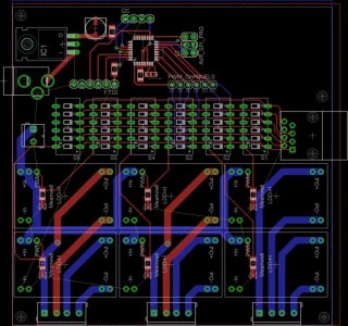
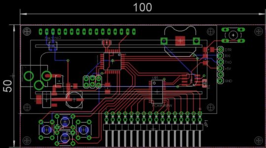
I stared playing around with the PCA9685 chip for a 16-channel controller...but here is a rough so far....haven't routed the lcd or temp sensors yet....maybe i'll throw BT or WiFi into it also....
Nice!
The PCA9685 is a cool chip.
I know you said this is a rough beginning just want to suggest you drive
the LCD backlight (PIN 15) with a transistor or MOSFET to take the load
off the ATMega PIN 1.
Since you are using a PWM pin to drive the LCD backlight you will be able
to dim the LCD backlight. Bonus.
I will be following.
Good work,
-BB
Similar threads
- Replies
- 3
- Views
- 2K
- Replies
- 46
- Views
- 13K