Meanwell LDD driver: for those who want to dim to 0 using Arduino

I burn the bootloader & the main sketch to the raw chip prior to soldering it in. The only reason I included a FTDI connection on the board was for reading the serial output.LOL Here's my thread that explains how to "Burn your own"- http://reefcentral.com/forums/showthread.php?t=2197597

Very cool.
I had no idea those TQFP sockets existed.
I have always added a 2x3 pin header to my designs and use a USBtiny.
I'm going to have to find one of those sockets.

Breaking out the FTDI connector is always a good idea in my opinion for debugging, serial motoring, data logging, and or reprogramming.

Nice job.

Thanks,
-BB
 
Last edited:
Since he released the design files 5 days ago, I doubt anyone got the boards printed and shipped to them. Maybe O2 has some ;)


I guess I'll say that I had some. The first batch of 10 is gone. They've been snapped up by Forum members, Lol. My PM box has been very active with messages from other members seeking them also, so I ordered enough PcB's and the associated parts to build 20 more.
 
I'm in need of 4 LDD pcbs.
I'm looking for
3 LDD-H pcbs
1 LDD-L pcb

I prefer the ones with resistors and jumpers but will def. consider the others

shark boy
 
Pardon me if this is a dumb question, but I've seen several DIY LED builds that use the Chester's Garage LED Power Shield with an Arduino for LED dimming on up to four channels.

http://www.chestersgarage.com/new-store/index.php?main_page=product_info&cPath=1&products_id=6

From what I can see, the O2Surplus 4-up and 5-up boards provide roughly the same capability at a fraction of the price (ie. I can build one for <$50 vs $150+ for the Chester's shield).

If my goal is to use the PWM outputs of an Arduino-based controller (Typhon, Jarduino, etc) through an O2Surplus board to drive & dim several strings of LEDs, what am I missing that the extra $100+ for the Power LED Shield would get me (other than "being on a shield")?
 
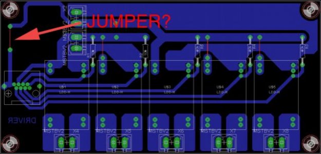
Hello here's my full home diy home iteration for LDD based on this topic.

The layout : single layer 150x70mm with two power supply possibility through mooex connexion, PWM RJ45 connection to Arduino and

13060510431012463311265533.png


So the board physicaly built

13060908055812463311276484.jpg


RJ45 interconnection board to Aduino

13060908153412463311276524.jpg


13060908055812463311276486.jpg


Ligthning result. It's a 3x20W custom multichip (left one on picture)

13040704103312463311058166.jpg


13060908153412463311276526.jpg


I use for moment 3 chanel from LLD board so have two more possibility on board for spectral supplementation
Marc
 
Hi Marc, can I ask where did you get the shield in your third photo will all the wire connections on the board? Thanks---Rick
 
Hi Marc, can I ask where did you get the shield in your third photo will all the wire connections on the board? Thanks---Rick

Hi Rick,

It's a friend Diy layout and solder work. Baord was etch by Itead studio. It has RTC on board. I really fine shield with good acces to screw connections

13060107312312463311252205.jpg


Marc
 
Pardon me if this is a dumb question, but I've seen several DIY LED builds that use the Chester's Garage LED Power Shield with an Arduino for LED dimming on up to four channels.

http://www.chestersgarage.com/new-store/index.php?main_page=product_info&cPath=1&products_id=6

From what I can see, the O2Surplus 4-up and 5-up boards provide roughly the same capability at a fraction of the price (ie. I can build one for <$50 vs $150+ for the Chester's shield).

If my goal is to use the PWM outputs of an Arduino-based controller (Typhon, Jarduino, etc) through an O2Surplus board to drive & dim several strings of LEDs, what am I missing that the extra $100+ for the Power LED Shield would get me (other than "being on a shield")?


From what I can see, the basic shield costs $40 then you have to add the cost of each RECOM driver added to the shield. The RECOM drivers cost $30 each (1000ma version). There's your extra $120, and it's just for the drivers.
You could by 6 MeanWell LDD-1000H for the same cost as 1 RECOM, if you know where to shop.LOL LDD-1000H | Mean-Well LDD-1000H | USA Warehouse

If you really want an ARDUINO LDD-H shield, let me know, and I'll re-post the build files.
 
Ya Marc, the screw connections make for a neater job. I put together a Jarduino set up,and it was kind of hard soldering to the shields to get it all working and I had to add a RTC to it also. Your screen readout lookes like a Jarduino.---Rick
 
Ya Marc, the screw connections make for a neater job. I put together a Jarduino set up,and it was kind of hard soldering to the shields to get it all working and I had to add a RTC to it also. Your screen readout lookes like a Jarduino.---Rick

Rigth it's jarduino soft.

Marc
 
Idefixes,
Nice home made single sided driver board.
What is the purpose of the ground jumper for the RJ45 jack?

Good work,
-BB
 

Attachments

  • driver.jpg
    driver.jpg
    36.1 KB · Views: 4
Back
Top