Meanwell LDD driver: for those who want to dim to 0 using Arduino

Welp my Meanwell SP-320 just died on me, so now I need to research a new power supply. It says 3 year warranty although I have a feeling they'll find some reason to get out of it. It's not like the thing was over the tank either, and was WELL out of any splash distance, perhaps ambient humidity in the 50+ range is enough to kill it, I checked out inside and didn't see anything that would scream to me that something ugly happened.

Finding power supplies that are encapsulated, at least 48 volts, and a few hundred max watts, and somewhat inexpensive is a bit tricky. Anyone have any ideas?

try for the warranty replacement/repair, just don't volunteer any information about how it was used just that it stopped working. overheating can kill them if there isn't adequate ventilation over time.
 
Rather Dumb question...

Which power supply is recommended to be used with 4UP version when all 4 LDD's are in use with 3w LED's.

....
Bhaskar
 
try for the warranty replacement/repair, just don't volunteer any information about how it was used just that it stopped working. overheating can kill them if there isn't adequate ventilation over time.

Oh definitely. although I did notice there's a bit of corrosion over the fan intake which is where it may get me in trouble. And I looked under the fan, and there's more there too. But then again that could be normal simply because that's where humid air in general could exit.
 
I finally figured out my problem. After getting frustrated last night I have up and today I started from square one. The first led in my string was bad. After hooking up to the next one in line they lit up. The rest of my leds won't be here till later this week so I will finish it then. This is a pretty big build and as soon as I have it done I am going to start a build thread.
 
I'm having a problem getting PWM working on my ldd-700hw. It works fine at full brightness, but connecting the PWM pin to my arduino results in no change.

I'm using a hydra-reef for the controller with slightly modified stock firmware (from terahz). It powers my meanwell ELN without issue. I'm using pin 10 for the ELN (with shield) and now pin 9 for the LDD.

I can measure the voltage decreasing when I lower the PWM value (around .745 v at 20% duty), but I have no way of actually measuring it other than with a multimeter.

I have it wired using a 1k resistor on pin 9, and arduino ground tied to Vout - pin on the LDD. No 10k resistor between Vout- and PWM as of yet.

Is there anything else I need to do in the Arduino or wire it differently to get it to work?
 
I might be wrong but I think you need to tie the arduino ground to the vin- not the vout- Someone correct me if I am wrong. But that's how I just got mine working literally 5 minutes ago
 
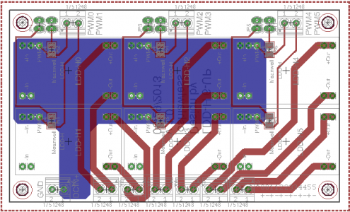
This thread has inspired me to try to learn PCB layout. I probably botched some things I don't completely understand, but attached are copies of the .brd, .sch and gerber files I created for a 6-UP LDD-H board with pull-down resistors activated by jumpers. It's pretty tight to fit everything on the 100x60 cm board, and the labeling is a bit weak; but if anyone with more experience wants to take a look and see if they spot any reason why it wouldn't work, I'd be grateful for the input.

Areas I'm concerned by: spacing between the screw terminals, spacing between the LDD-H devices, spacing between the jumper headers.

Also, in the mac version of Eagle, the polygon ground pours don't show up when I open the file until after I run ratsnest. They're present in the Gerber files. Not sure if that's a setting problem, or an error in my method of saving.

Nice work for your first go.
A couple of observations:

1) You will need to make the traces for DCIN+ much larger. I would make a Signal BUS DCIN+ using polygons.
EDIT: You could also simply rename your bottom ground polygon from GND to DCIN+
Assuming you were using LDD-1000H's.....
If you had all 6 LDD's running at 100% you need to supply up to 6 amps plus ~20% headroom. 7.2 AMPS!
Using the calculator linked below using 2oz^ft copper boards your traces need to be 90 mils yours are 16 mils.


2) Likewise you should check the datasheet for your DCIN screw terminal and ensure it can handle the current.

3) You will also need to increase the trace width of all of your Outputs LED+1 / -1 thru LED+4 / -4. At full power they need to handle 1 amp plus ~20% headroom.

4) Invoking Ratsnest when you first load a board file to show pours is normal for Eagle with all operating systems. It makes sense to me as I do 99.9% of my work without the polygons filled. Easier on my eyes.
You also might want to make one of your GND polygon perimeters larger than the other. It makes it much easier to choose one or the other. You can make them larger than the perimeter of the board. Eagle will only fill the board never outside.

There are some good Trace Width calculators on the net.
Here is one I have used. http://circuitcalculator.com/wordpress/?p=25/


Cheers,
-BB
 
Last edited:
I might be wrong but I think you need to tie the arduino ground to the vin- not the vout- Someone correct me if I am wrong. But that's how I just got mine working literally 5 minutes ago

Yup that was it. Somehow I screwed it up, but amazingly didn't kill my arduino or drivers :D

Thanks!
 
If you are going with 48 volts then I think the common one would be 3.3 amps. That is about 158 watts.

the current you'll be running also needs to factor in. 3.3A @ 48V will be fine if running 700mA LDDs however if using the 1000mA version with full strings you'll potentiall be drawing over 179watts which exceeds that PSU.

@700mA driver current you'd be pulling 125watts which will pretty nearly max out the PSU when considering that the LDDs will consume some power as well.

if using less than 14 per string then you need to figure out the projected total watts being used by the leds at full power and use that number to size the PSU, keeping a 15-20% overhead is a good practice with the PSU selection as if they are running at max they have better chance of failing due to heat build up, etc.
 
I finally figured out my problem. After getting frustrated last night I have up and today I started from square one. The first led in my string was bad. After hooking up to the next one in line they lit up. The rest of my leds won't be here till later this week so I will finish it then. This is a pretty big build and as soon as I have it done I am going to start a build thread.

was the bad one a new LED? it happens but not real often. Did you perhaps hook it up backwards? been there, done that :)
 
joshlawless,
Here is a possible solution:


-BB
 

Attachments

  • TEST.png
    TEST.png
    39.1 KB · Views: 4
joshlawless,
Here is a possible solution:
-BB


Thanks for all your helpful input. I was working up an alternative layout based on your previous post -- here's what I've got so far:
6UP_LDDH_Board_Top_1.1.png

6UP_LDDH_Board_Bottom_1.1.png


Now I understand why there were multiple DCIN+ and GND connections spread over multiple screw terminals in O2Surplus and RRasco's 3-, 4- and 5-up versions. I've added another two screw-terminal block, and increased the trace sizes for the LED outputs, and built a hefty bus for the DCIN+.

I've also tried to improve the labeling somewhat.

V1.1 is attached.
 
Last edited:
Thanks for all your helpful input. I was working up an alternative layout based on your previous post -- here's what I've got so far:
6UP_LDDH_Board_Top_1.1.png

6UP_LDDH_Board_Bottom_1.1.png


Now I understand why there were multiple DCIN+ and GND connections spread over multiple screw terminals in O2Surplus and RRasco's 3-, 4- and 5-up versions. I've added another two screw-terminal block, and increased the trace sizes for the LED outputs, and built a hefty bus for the DCIN+.

I've also tried to improve the labeling somewhat.

V1.1 is attached.


That's looking good! Those traces are plenty "hefty" and will work fine.
 
That's looking good! Those traces are plenty "hefty" and will work fine.

Super ignorant question, but have I got those screw terminals attached the correct way (so that the wires come from off the board)? I'm not sure which side is which from looking at the design in Eagle -- there's a little triangular arrow opposite pin 1 that points in towards the PCB in the current design. Did I get that right?

Thanks!
 
Back
Top