mr.wilson
.Registered Member
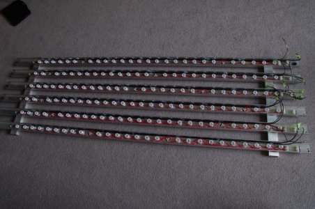
This is good info. I just got done soldering three of the 60W combos about thirty minutes ago. I contemplated soldering to the pads on the frame block but I was not sure how to apply enough heat there. (I'm not a pro)
Maybe I should give it a try.

")
Soldering to the block is easy. Use all-in-one solder with flux and don't let the iron get too hot. Remember to double check polarity before you solder.