Minimalistic multichip DIY LED build

They don't blend very well in my opinion, but many people are happy with alternating fixtures (blu/wht/blu/wht). The directional nature of LEDs also creates blue & white zones in your tank so unless you are rotating the fixtures on a mover, the corals will be adversely affected.

Hybrid (mixed) chips are the way to go and cost should be about the same.

In my opinion the more LED's you have the less zoning you have. However other things like raising the fixture will help redice the zoning. When you add lenses you can also end up increasing the posibility of the zoning effect which is why I ended up removing the lenses from my fixtures. Now keep in mind some individuals do like some this zoning.

Keep in mind that closer together two different colored chips are the less the chances of getting a visiable color zone effect. So a multichip with different colors right into the same chip will not zone so much as it would with using several different chips spaced apart.

I tried going with 20 watt Chips on a 40 gallon tank and did not like the zoning effect as there was a space between the colors resulting in color shadows. But with 3 Watt LED's the shadows were repeatedly overlapped to the point they became unnoticable.

I think you would see this problem even when you simply run some stunner LED's like adding 3 or 4 RED 3 Watt LED's to a big build they become hard to create an even light distribution from just those few chips.
 
question when your building your fixture why would anyone wanna have over 5 power cords isnt their a dimmable driver that will work many 50 watt royal blue multi chipe or a dimmable driver that will run many 50 watt 10,000 k cool white leds?

Yes it has to do with your Driver and LED selection. With a Meanwell HLG-320 series driver you could run 6 50 watt LED's off of one driver. However in some cases the driver cost makes it less expensive to run two smaller drivers compared to one large driver. The other thing is non-dimmable drivers are generaly less expansive and you can eaisl;y then work with 3 timers for a pre-dawn-post dusk circuit, dawn to dusk circuit, and a mid day circuit.

Howver mixing colors on a driver does depend on matching electrical specs of the LED's which is not always possible when your mixing colors and even manufacturers in some cases.
 
I have been thinking of doing something with LEDs. I think this thread just pushed me over the edge. Now if I can just find my wallet....
 
Well, I ordered my heatsinks from RapidLED.

http://www.rapidled.com/6-x-20-black-anodized-aluminum-heat-sink/

Each unit has about 1,000 square inches of surface area. The cost for three with the splash shields was just about $40 more than ordering and shipping aluminum C-channel since I couldn't find it in town.

Now to have the waterjet guy at work make me a center punch template!

According to the guy from AC-RC, the chips need > 32sq cm per watt of surface area for unassisted cooling. If I bump it up to 50sq cm per watt for a significant buffer, that's enough area for 39 ten watt chips...without a fan. Not too shabby!
 
another minimalistic example

another minimalistic example

OK, here are some pics to show some assembly and mounting ideas.

I continued the minimalistic design, but I didn't want to glue the LEDs to the heat sink, as the heat sink is a significant cost, which I may want to use with different LEDs. Instead, the LED, reflector and lens are held in place by the oval face plate. No glue is needed on any of the parts. Of course, you still need heat sink grease (not glue though).

I had to fab a few parts out of standard aluminium bar stock, as shown here (i had access to band saw and drill press).
LEDparts.jpg

Here's a 60W (up to 151W) 10K/Blue LED from AC-RC attached to Noctua NH-D14 heat sink. I like their products, and their fans are some of the best (quite, but move losts of air, and have >150,000 MTBF). I'm using 60 deg lens, so the LEDs can be mounted high over the aquarium. The gray ring, held in place by gravity, was cut from some PVC fitting, and insures LED cannot slide out, but it's not really needed.
LEDasymbled.jpg

The two aluminum side bars allow the fixture to be hung using SS 1/32" (0.8mm) cable, which is almost invisible, but can support 150 lbs (68 kg). I like the industrial look, especially since my aquarium is relegated to an unfinished basement.
LEDhanging.jpg

Here are the LEDs at 100% power. The aquarium is 48x18x12.
LEDfull.jpg

Here, the left LED is as 10% power (low as it will go using MW HLG-150H-36B), while the right is at 100% power.
LED10L100R.jpg

I'm using an Apex VDM module to control the LED drivers (0-10v). Works perfect, but minimum of 10% output is still too bright to run as moon lighting (as others have noted).

Overall, I like it. My aquarium is extremely shallow (< 12in), but the LED pendants are high and out of the way. I'm running them at 40% power right now. We'll see how the corals like it.

Lighting color is similar to what I had before (4 54W T5HO, 2 10K and 2 Blue), but brighter, and with tons of shimmer (almost too much). I'll see if I can get some PAR readings at some point.
 
Last edited:
Joe,... Nice Post! I like your setup.
Ya, some par readings would be nice + hanging height + drive power, would be a nice gauge to go by.---Rick
 
Thanks Rick!

LEDs are about 19 in above the top. At full power, those LED's draw 4.4 Amps, at ~34 V. with the Mean Well driver. Since the max current of the epistar chips is 4.2 amps for the 6 lines of 10 LEDs, I don't drive them at more than 90% of full. But, I will keep them at only 40% until corals acclimate to the new light source.

If I get a hold of a PAR meter, I'll see what kind of readings I get at different power levels.

-joe
 
Thanks Joe, Ya if you get a par meter, would be interesting to see with your tank depth...what you want to power them at---Rick
 
Well, I ordered my heatsinks from RapidLED.

http://www.rapidled.com/6-x-20-black-anodized-aluminum-heat-sink/

Each unit has about 1,000 square inches of surface area. The cost for three with the splash shields was just about $40 more than ordering and shipping aluminum C-channel since I couldn't find it in town.

Now to have the waterjet guy at work make me a center punch template!

According to the guy from AC-RC, the chips need > 32sq cm per watt of surface area for unassisted cooling. If I bump it up to 50sq cm per watt for a significant buffer, that's enough area for 39 ten watt chips...without a fan. Not too shabby!

hey im using those heat sinks for my current build as well ! i plan to cool a 100w chip and 2x 20w chips on each one with 3 fans on each one do you think this will work well? i probably wont be running them at 100% either
 
Wow Tom,...All you need is auto fish feed, and the only other thing you have to do, is look at it !:crazy1:
Are you going to set the D.C. up in the pvc pipe with your Zalman? I'm curious what temp. the cooler can hold the chip to.
Also what are you using for your 12 conductor wire? Have a Good Day---Rick

I am using 12 conductor grey (it'a actually a dark grey) audio cable nonplenum from mcmaster-carr. It's rated to 300v, and it's only .21" diameter. Very nice stuff, and like $.67/foot.

Yep, I have a DC to go on the CNPS8900, and it will go in a 4" DWV PVC coupler like the last one.

I am automating everything because we are planning on leaving town for 3-6 weeks in the somewhat near future, taking some paternity leave to go see my parents.. I don't trust my brother in law to do more than feed... Just gotta keep an eagle eye on the levels and figure out my dosing.
 
Know what your saying Tom. Mine is pretty much automated...runs like a top for months...then Murphy's law, I leave for a few days and everything that can stop working does ! return pumps-dosers-auto topoff-lighting :headwallblue:
Thanks for the wire input. I looked at McMasters, but not audio cable. I'll look again. What gauge are you going to use. I was thinking 14 cond. 10 for chip-2 for fan, and 2 for temp.? Someone had mentioned HDMI cable, but I have no idea if it would work. I was also thinking about a connector like Ron posted, so I can undue and remove each fixture if necessary.---Rick
 
Mr Wilson did you ever post a link to those ones you used? Or is it a hush/hush or ToS violation? 5 channels seems awfully sexy in a mixed chip.

The chips in the pictures I posted are from one of the sponsors here on RC. As a reseller of products from that sponsor, I am not permitted to disclose the name of the sponsor. I could disclose the source if they were from a company I don't deal with and were not paying sponsors, providing they were not on a ban list for prior RC infractions. Simple enough :)
 
Well, thats not sounding like I wanted :( 
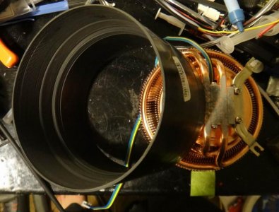
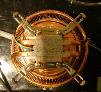
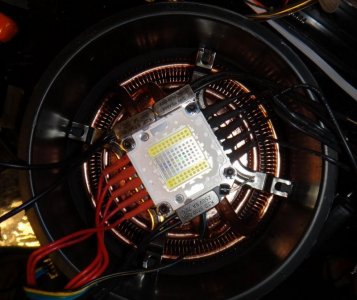
. I would do a hybrid chip but I would need a 100w-white and 100w-blue independently drivable.

I agree, 3 or 5 channel multichips are the only way to go. One channel chips shift to a more blue colour when dimmed (dawn/dusk) but nothing like what we are used to with pure royal blue phases. You could use PAR38 LEDs for dawn/dusk and run the 100w mutichips at 100% during the day.
 
In my opinion the more LED's you have the less zoning you have. However other things like raising the fixture will help redice the zoning. When you add lenses you can also end up increasing the posibility of the zoning effect which is why I ended up removing the lenses from my fixtures. Now keep in mind some individuals do like some this zoning.

Keep in mind that closer together two different colored chips are the less the chances of getting a visiable color zone effect. So a multichip with different colors right into the same chip will not zone so much as it would with using several different chips spaced apart.

I tried going with 20 watt Chips on a 40 gallon tank and did not like the zoning effect as there was a space between the colors resulting in color shadows. But with 3 Watt LED's the shadows were repeatedly overlapped to the point they became unnoticable.

I think you would see this problem even when you simply run some stunner LED's like adding 3 or 4 RED 3 Watt LED's to a big build they become hard to create an even light distribution from just those few chips.

It seems that no matter what multichip question is asked, you have a single chip answer :)

The human eye cannot detect the blue & white zones when they are close together, but the corals are still experiencing the colour separation. Where we can see it, is in the purple and yellow (disco) shadowing on the substrate and under rocks.

One factor that can amend colour zoning is refraction with ripples in the water. Water bends light and may compensate for the poor mixing of "pegboard" single LEDs. It will not however, mix blue & white multichips that are positioned several feet apart. Even multichips with all blue on one side and all white on the other can have zoning.This is compensated by neighbouring fixtures though.
 
OK, here are some pics to show some assembly and mounting ideas.

I continued the minimalistic design, but I didn't want to glue the LEDs to the heat sink, as the heat sink is a significant cost, which I may want to use with different LEDs. Instead, the LED, reflector and lens are held in place by the oval face plate. No glue is needed on any of the parts. Of course, you still need heat sink grease (not glue though).

I had to fab a few parts out of standard aluminium bar stock, as shown here (i had access to band saw and drill press).
View attachment 206644

Here's a 60W (up to 151W) 10K/Blue LED from AC-RC attached to Noctua NH-D14 heat sink. I like their products, and their fans are some of the best (quite, but move losts of air, and have >150,000 MTBF). I'm using 60 deg lens, so the LEDs can be mounted high over the aquarium. The gray ring, held in place by gravity, was cut from some PVC fitting, and insures LED cannot slide out, but it's not really needed.
View attachment 206646

The two aluminum side bars allow the fixture to be hung using SS 1/32" (0.8mm) cable, which is almost invisible, but can support 150 lbs (68 kg). I like the industrial look, especially since my aquarium is relegated to an unfinished basement.
View attachment 206647

Here are the LEDs at 100% power. The aquarium is 48x18x12.
View attachment 206648

Here, the left LED is as 10% power (low as it will go using MW HLG-150H-36B), while the right is at 100% power.
View attachment 206649

I'm using an Apex VDM module to control the LED drivers (0-10v). Works perfect, but minimum of 10% output is still too bright to run as moon lighting (as others have noted).

Overall, I like it. My aquarium is extremely shallow (< 12in), but the LED pendants are high and out of the way. I'm running them at 40% power right now. We'll see how the corals like it.

Lighting color is similar to what I had before (4 54W T5HO, 2 10K and 2 Blue), but brighter, and with tons of shimmer (almost too much). I'll see if I can get some PAR readings at some point.

This is where the 50/60w chips work out well, driven at 150w.
 
I have some pictures of my current dream chip build to show up..

No idea if they will come out in order but here they are:

A picture of the 4" DWV coupler with the stop ring machined out, and one end bored out to accomodate the size of the CNPS8900.

The coupler with 4 little pieces of ABS pipe glued in as blocks to screw the mounting bracket to.

The heatsink with bracket on, you can see where I have marked the outside edges to cut away to fit in the pipe. I also had to grind parts away where the LED is mounting, you can see that as well near the corners of the heatsink base.

Heatsink mock installed in the tube. To get it in there you slide it down and then turn until the mounting bracket tabs line up with the little plastic blocks.

A picture of the tool I use to cut ABS rings into small pieces. This thing works absurdly well for this.

I'm posting this stuff while waiting for the glue to set up some before I drill holes for the mounting screws.
 

Attachments

  • Tube showing machining.jpg
    Tube showing machining.jpg
    66.3 KB · Views: 6
  • Detail of tabs inside tube.jpg
    Detail of tabs inside tube.jpg
    77.6 KB · Views: 5
  • Mounting bracket.jpg
    Mounting bracket.jpg
    87.2 KB · Views: 5
  • DC build ABC coupler showing retainer detail.jpg
    DC build ABC coupler showing retainer detail.jpg
    69.9 KB · Views: 6
  • How to cut an ABS ring into bits.jpg
    How to cut an ABS ring into bits.jpg
    83 KB · Views: 6
Back
Top