Must-haves for EASY DIY controller?

After some time I have finally solved -5V issue, inproperly solded 10uF capacitor on pins 2 and 4, even everything looked OK.

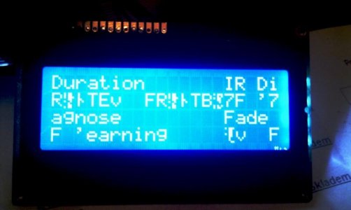
I was trying to setup remote, I connected TSOP4838 to digital 6 on master and used NEC TV on my Logitech Harmony one, but nothing happens. Any clue what could be wrong? What remote are you guys using?
 
Hamato, I just cut it for a snug fit. Cut it just to size and file it from there until you can fit the lcd. You can always glue it on there too :)

marcer, is the ir setting enabled in the firmware? Dis you go through the remote learning process?
 
"The trick is called EEPROM"
OK all worked as Terahz said, might add that I removed the battery and powered off for a few seconds then back on for the clock to reset. One thing though now when I turn the power off to the hydra then back on some time later it starts at the point I turned it off. That cant be right. Any comments
 
marcer, is the ir setting enabled in the firmware? Dis you go through the remote learning process?

It was stupid error, my HarmonyOne universal remote was set incorrectly. Now I can use NEC codes, I tried also RC-5 Philips condes but only every second press was received (RC-5 sends two different codes for one button to prevent repeat errors).

I'm really sorry with problem again, but after I enter menu I get strange characters on the screen and when I scroll down it becomes worse and worse. See the picture. After pressing select sometimes correct screen (e.g. setting of levels, etc.) is show, sometimes not. After I get again into menu, it look almost normal except menu cursor, but after scrolling it starts to corrupt again. I can enter this way all setups except clock setup.

I redownloaded and uploaded to Hydra both complete Prod and Slave Revision 65, but same problems. Any clue? Could it be HW or is it SW?
 

Attachments

  • IMAG0846.jpg
    IMAG0846.jpg
    32.9 KB · Views: 12
Suppose this may be the best place to ask. I am looking at employing the use of the MCP23008 for several tasks in my controller. First is relays. I have it up and running using some code and libraries obtained from adafruit. I the code doesnt appear to allow me to address multiple MCP units. ex: I want one for power center, one for dosing pumps and one for LCD. Any input on using the libraries from this project and inputting it into my own code? Do you have any code examples by any chance?

Thanks in advance!
 
Hi all! Been lurking around these forums for a good bit now and was looking into building a controller for my current build, a 29 gallon oceanic cube. I know this might be overkill for the tank itself but figured that I would want to monitor certain aspects, such as temp and pH. As well as control a DIY LED rig that would simulate sun rises and sets as well as moon phases. Would also be cool to possibly make it control wave making, but that's for later.

Looking to see if anyone has the PCB only and if not may look into getting a batch order that we could organize outside of these forums as per the rules.

As always keep up the good work guys! Definitely gAve me a new hobby that I can appreciate :)
 
Suppose this may be the best place to ask. I am looking at employing the use of the MCP23008 for several tasks in my controller. First is relays. I have it up and running using some code and libraries obtained from adafruit. I the code doesnt appear to allow me to address multiple MCP units. ex: I want one for power center, one for dosing pumps and one for LCD. Any input on using the libraries from this project and inputting it into my own code? Do you have any code examples by any chance?

Thanks in advance!

All I2C devices on a bus must have unique addresses. From a high level there's kind of two sides to this - software and hardware.

In the hardware, the MCP23008 has part of it's address "hard coded" and part user-controlled via address pins on the package (you either tie them to GND or Vin to set your desired address). So, the first challenge is to choose unique addresses for each MCP23008 in your project. As far as I recall, the "official" MCP23008 breakout associated with this project has jumpers for the address pins, so it's no issue if you are using that hardware. If you are using some other hardware, you need to figure out how to set the address pins.

Next, you need to alter your software so each time you're communicating to an MCP23008, you're calling it at the correct address for that instance of the chip, i.e. the address that matches the way you configured the address pins on that particular chip. This will vary depending on the sketch or library you're using.

IMHO the easiest thing would probably be to abandon the adafruit code if it's not working and use the MCP23008 library that terahz wrote as part of this project, since it allows you to specify an address for each instance of the mcp23008 you have in the project.

If you need more details please let us know, but I figured it might be valuable to start with a high level overview.
 
Thanks dwzm! I got the relays working with the adafruit code but I would like to set myself up for multiples as I am planning for another relay panel, an LCD and possibly a remote port expander. Do you have any code samples that will get me up and running on the hydra libraries? My next project is the LCD controlled by an Mcp as well. I am struggling to understand how to enter addresses though. I understand that the binary address is 0100xxx based on pin placement, but how do I turn that into the 0.xx style address that most code seems to use? If you have any samples for the LCD code that would be much appreciated as well.

Thanks again, you guys have been amazing help
 
Check on the google code site mentioned in this thread and on terahz's repository, also mentioned in this thread - both are also linked from the wiki at http://hydra-reef.com/wiki/Home. There are plenty of examples of the code, both from a generic sense and for specifically using the chip for the functions you're describing.
 
First off, been following this thread for ever, it's inspired me to try my own DIY controller. I have gotten a little ways into my project but now I am stumped.

Can someone please tell me how much current and voltage the Chauvet SR-8 needs to trigger the relays? I am a total newb to electronics and attempting to build my own controller using an Arduino Mega. So far I have a working digital clock and temp guage and am now starting work on the programmable outlets.

I was assuming I could just use the Arduino's PWM outputs to trigger the SR-8's relays individually but it's not working so I am assuming a need a stronger voltage or current. Right now I am getting about 4.6 volts out of the Arduino.

Any help would be great.


Sorry to hiijack the thread, hope it's OK.
 
Ok, so I found the pinout to the SR-8. Apparently I need +12v to close the relays, the Arduino only gives me around 4.6 max. I need something to step up the voltage in between?
 
Last edited:
WindowMaker, from my code take:
mcp23xx.cpp
mcp23xx.h

Create a new arduino project and import the .h files (along with Wire.h)

Initialize the mcps:
MCP23XX relayset_1 = MCP23XX(RELAY_MCP_DEV_ADDR_1);
MCP23XX relayset_2 = MCP23XX(RELAY_MCP_DEV_ADDR_2);
.
.
as many as you want

Then all you do is call relayset_1.set(registers,value); relayset_2.set(registers,value) ...

That's it.

I've written a little helper class in I2CRelay.cpp and I2CRelay.h that lets you do things like relay.enable(pin_number); relay.disable(pin_number); ... (check the .h file)

If you want to use the helper class you will have to modify it slightly to work with multiple MCPs, but other than that it should do what you want.
 
wavers, I haven't used the Chauvet setup but I assume the 12V are needed to power the relays and then you use the 5V from your arduino (doesn't have to be PWM, regular digital pin will do just as fine) to turn on/off that 12V to the relays. I'd wait for someone who has used it to chime in.
Since you're new to electronics, be extremely careful! These relays will be breaking 110V, and you don't want to play with that.


That's what I thought until I started messing with it. The only way I could get the relays to turn on was to put 12v to the the pin labeled +12 and the negative to the pin of the desired relay you want to turn on.

I guess I should say I'm not a total newb as I am in my last semester of an Electronics Engineering program. Let's just say this is my first on my own project. :lol2:
 
I hope you know that, technically, you're more qualified to solve this problem than any of us are. :D

We need some specs or documentation before we can really help. Do you have a link to a product page or datasheet?

The MCP23008 relay breakout board will probably work but it's hard to say for sure without some more information. Or if you really did want to use GPIO pins from the Arduino itself (might seem like the simplest option but IMHO isn't always the best) then you probably need a way to get the Arduino to switch a 12v signal, so you'd likely need a 12v source and a transistor driven by the Arduino's output pin.
 
I guess the part I am still struggling with is the (registers, value) part. Though I understand the hardware aspect of externally biasing the relay pins, I dont understand the software aspect. ex: if I were to put all 3 address pins to ground, what would I put in that part of the code?

Thanks again for your awesome help!
 
Back
Top