My Neptune Apex web interface compatible DIY reef controller

More sharing.

Here is my box for my frag tank.... not all your bells and whistles but will be perfect. Also, I got these to fit my LCD and the Sonar in.....

http://www.ebay.com/itm/New-Plastic...600?pt=LH_DefaultDomain_0&hash=item5d4c974920

sonar.jpg

controller.jpg
 
Last edited:
I was planning to put the rj-45 plugs external, rather than cutting holes in the project box. Either via a biscuit jack with inserts, a surface mount wall plate junction box with inserts, or a patch panel. You can get 12 port patch panels for 15 bucks, providing a total of 48 pairs you could run external from there.

The chauvet brand is I assume a more well known name and probably built more robust, but i've seen a couple other people build switched power supplies from a gutted apc battery backup, and one of these. http://www.amazon.com/Technical-Pro-PS9U-Supply-Charging/dp/B0057RL6DQ/ref=pd_cp_MI_1 Which actually includes a 5v circuit that could be used to power the relay board itself.

Could http://www.amazon.com/American-Pc-1...F8&qid=1412787198&sr=8-5&keywords=american+dj
or http://www.amazon.com/Eliminator-Lighting-Controllers-PL-07-Accessory/dp/B000GASJF2/ref=pd_cp_MI_0 be viable options as well?
 
nice. I see you just use uln2803 and db9 to connect to an "unmodified" chauvet?

how much space does the audio jack take inside the chassis? I can't find any technical diagram with dimensions for that connector.
I'm thinking if I replace my PCB mounted jacks, if there will be enough space for these chasis mounted jacks.

The advantage of using stereo jacks: they are cheap, it is way easier to drill a round hole than to make a square hole, and if you accidentally trip on one, it will disconnect from the controller and not drag the whole controller down and yet provides a secure enough connection for this application. :)

The total length is about 7/8". take a look. inside would be about 3/4"

connector.jpg
 
I was planning to put the rj-45 plugs external, rather than cutting holes in the project box. Either via a biscuit jack with inserts, a surface mount wall plate junction box with inserts, or a patch panel. You can get 12 port patch panels for 15 bucks, providing a total of 48 pairs you could run external from there.

The chauvet brand is I assume a more well known name and probably built more robust, but i've seen a couple other people build switched power supplies from a gutted apc battery backup, and one of these. http://www.amazon.com/Technical-Pro-PS9U-Supply-Charging/dp/B0057RL6DQ/ref=pd_cp_MI_1 Which actually includes a 5v circuit that could be used to power the relay board itself.

Could http://www.amazon.com/American-Pc-1...F8&qid=1412787198&sr=8-5&keywords=american+dj
or http://www.amazon.com/Eliminator-Lighting-Controllers-PL-07-Accessory/dp/B000GASJF2/ref=pd_cp_MI_0 be viable options as well?

there is no right or wrong way to do this. if it works for you, do it.

the way I did it, I was going for a self contained all in one box solution.
 
nice. I see you just use uln2803 and db9 to connect to an "unmodified" chauvet?

how much space does the audio jack take inside the chassis? I can't find any technical diagram with dimensions for that connector.
I'm thinking if I replace my PCB mounted jacks, if there will be enough space for these chasis mounted jacks.

The advantage of using stereo jacks: they are cheap, it is way easier to drill a round hole than to make a square hole, and if you accidentally trip on one, it will disconnect from the controller and not drag the whole controller down and yet provides a secure enough connection for this application. :)

Yep. using the unmodded SR8. My unit was not the exact same you have. Same brand and same model but my unit was smaller then the one you used. Using the separate project box for everything except the sr8 worked great... Again thanks for all the work you have done on this project.
 
How hard would it be to get the relay board controlled by a pcf8575?
would be so amazing to be able to run a 4pole 3.5mm to it!
the quest for a 4 pole splitter continues!
 
to hook up more devices to the i2c bus.
Currently, the connection to LCD is an I2c bus.

the pcf8575 is similar to the chip used in the I2C LCD backpack circuit (MCP28xxx).

I don't want to pay even $5 for these splitters. If you have space in your project box, you can just more TRRS jacks for additional I2C device connections. The LED control will be via I2C. You can also use the EZO atlas stamps on I2C, so potentially you can have 5 or 6 I2C devices attached to the controller (plus the RTC). Or if there is no more space to add more jacks on the controller box, you can build an I2C expansion box by using the one connection to the controller, then splitting it out to N connections on the project box.

You will have to modify or replace the whole outlet routines to use I2C for IO control. The routines cannot run inside an interrupt handler anymore, and must be run in the main loop. It can be done, just not going to be trivial.

So how about RJ11?

http://www.ebay.co.uk/itm/White-RJ1...g_Plugs_Jacks_Wall_Plates&hash=item1c3abc61fb
 
Last edited:
any connector you choose to use is fine.
in this case, the 3.5mm audio connector is chosen, and the issue is how to split the line.
I think the price for the splitters are rip-off price.
In case anyone finds one at a good price, please post here.

and before buying, make sure to contact the seller to confirm it actually has all 4 connections. I contacted the cablesonline seller link posted by rrbigdog before and seller confirmed all 4 contacts are connected.

I bought one recently from a US seller, and only 3 contacts are connected even though the plug is TRRS, the sleeve is unconnected. I got my money back on that one through ebay. Seller would not refund me unless I send back. I asked for a return label and seller wanted me to pay for return shipping so I opened an ebay case and got a full refund.

it is like this
$_14.JPG


turns out it won't work anyway unless your plug is those super slim connectors like those on iphone. Two normal sized connectors will not fit side by side on these splitters so I could not even use these to split the temp sensor onewire connection.
 
Screen Shot 2014-10-12 at 16.49.18.PNG

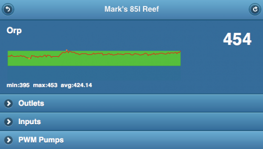
function getSparkData() {
if (sensoropen==false&&initialized) return;
for (var i=0; i<sensordata.names.length; i++) {
var c=[];
var sensorname=sensordata.names;
var max_=0.0;
var min_=600.0;
var total_=0.0;
var actualrecs_=0;
$.each(sensordata.record, function (j, rec) {
if (isNaN(rec.data)) {
c.push(null);
return true;
} else
c.push(parseFloat(rec.data));
actualrecs_++;
if (c[j]>max_) {
max_=c[j];
}
if (c[j]<min_) {
min_=c[j];
}
total_+=c[j];
});

$("."+sensorname+"_gr").sparkline(c,{type: 'line',width:"100%", height:'100',drawNormalOnTop:true,lineColor:'#ff0000', fillColor: '#356c9a', spotColor: false, chartRangeMin: 250, chartRangeMax: 550, normalRangeMin: 350, normalRangeMax: 450, normalRangeColor: '#5fbf00'});
$("#"+sensorname+"_mma").html("min:"+min_+"  max:"+max_+"  avg:"+parseFloat(total_/actualrecs_).toFixed(2));
}

D0ughb0y,

Could I have a bit of help please?

I need to identify the variables to populate the elements in red above so that each of the sensors in a simular way to the ORP fixed values?

Can you help please?

Thanks

M
 
you need to declare those variables and define the values, or just hardcode them as you did, as those values are really independent of the data values.
 
I resumed work on the program for pwm fan, and it seems I am unable to get a stable rpm reading, particularly at higher rpm. I am going to try a few more options to see if I can get this to work and if not, I might consider off loading the code to an arduino pro mini acting as I2C slave.

on my stand alone test code for the pwm fan, I get a very accurate rpm reading.

I was having network connectivity issues on my local network and fixed it recently and now my network connection seems stable now. no more random disconnections. I also noticed I have not seen my controller do an ethernet reset for several days now. I suspect I will be able to upload arduino sketch via tftp to my netload bootloader arduinos, but I have not tested yet, since I am using my spare ethernet shield on my test circuit. thanks to sorscode for hinting what was causing my network connection issues.

I also ordered an ESP8266 wifi module to play around with to see if can make the controller use a wifi conneciton. This is a very cheap wifi module. A seller from GA sells them for $4.08 each. We'll see how this pans out. I actually prefer the controller to have a wifi connection than a wired connection, but the cost of the arduino wifi shield is too high. If using this instead of wifi shield, you will need a separate SD card module though, but those are available for like $1.50 with level converter circuit built in. (SD cards operate at 3.3v).
 
based on atmega datasheet, the most accurate way to read frequency or rpm is to use the input capture function of the chip. I am currently calculating rpm by getting the time difference between pin state change, but this is not guaranteed if there are other interrupt routines. using the input capture to count events will limit the number of fans to 2, as there are only 2 pins available on the mega for this function. These are pins 48 and 49. This means I have to move the temp sensor onewire pin to another pin.
 
Back
Top