New DIY Ca reactor

GEBC, I noticed that the water moves from bottom to top in the first chamber. Do you every find that the water pump draws air from the top of that chamber? Would it be detrimental to the design if the water moved top to bottom in chamber one?
 
dvjanes said:
GEBC, I noticed that the water moves from bottom to top in the first chamber. Do you every find that the water pump draws air from the top of that chamber? Would it be detrimental to the design if the water moved top to bottom in chamber one?
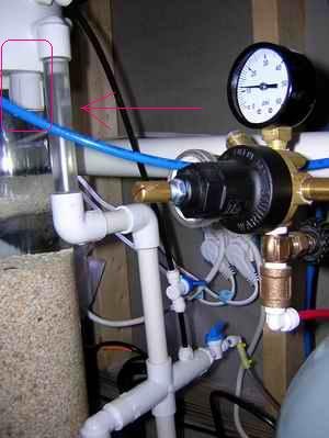
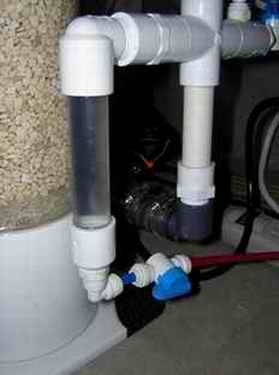
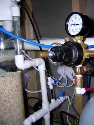
Actually this is the best design IMO for 2 reasons.
The first, having the pump take water from the top will prevent air from collecting up there. Only minor bubbles are allowed collect and soon they are sent through the pump chopping them up very fine which intern applies more Co2 to the water and it also will allow some air to escape out the effluent tube also if need be. I know some people have to release that collection of air on there reactors that pump from top to bottom. My reactor never collects any air in the top, just a few small bubble that soon find there way out.
The second, You don't want your media to get packed. The water traveling upwards along with the Co2 being injected seems to keep the media in the reactor more loose.
These are just my personal thoughts but this combination does seem to work the best. I'm sure others may have a different opinion.
 
Excellent! Thanks ReefRelated. Iââ"šÂ¬Ã¢"žÂ¢m going to be dry fitting the connections on my DIY-Reactor tonight and I wanted to get some of my questions answered before I get home from work.
 
Dvjanes, I have a co2 recirculation loop just above the pumps inlet that recaptures the excess co2, I have added a valve to the recirculation loop to control it precisely, the reactor runs just fine with this configuration, I also agree with Tony that this is the pumps inlet at the top is a superior configuration.>>>>>>>>>>GEBC
 
Dvjanes, I have a co2 recirculation loop just above the pumps inlet that recaptures the excess co2, I have added a valve to the recirculation loop to control it precisely, the reactor runs just fine with this configuration, I also agree with Tony, the pumps inlet at the top is a superior configuration.>>>>>>>>>>GEBC
 
Excellent Job GEBC! I got the plans from you in an e-mail a couple of weeks ago. I got all the parts but the acrylic. I found a place in Akron to get it. E&T plastics. 39.00 for 6'. I work in Akron so it will work out well. I am planning to use schedule 40 screw in caps for the plugs. Was there a reason you didn't go this route? Do you have any pictures of the changes you made to the reciculation loop and the connections from the co2 tank to the reactor? Thanks..Omar
 
Omar, Thanks for the complement ,the screw in caps for 4ââ"šÂ¬Ã‚ pvc are much harder to seal than the pressure plugs (screw in caps require tons of Teflon tape each time you remove them), the plugs only take about 6 seconds to remove, without tools. I will take some new pictures of the revised configuration and post them. >>>>>>>>GEBC
 
Thanks GEBC. Good point about the teflon tape. I had thought about this but then reasoned that they should be water tight due to them being used for plumbing. Not that this would hold true in function. I don't really know if they are designed for use under pressure. I will error on the side of caution and order the caps. Thanks again for all your help and generosity in sharing your plans with everyone. Hopefully I'll be posting my pics soon.
Omar
 
Updated photos

Updated photos

Here are some updated pictures of the bubble counter and co2 connections.
 

Attachments

  • bubble counter=co2.jpg
    bubble counter=co2.jpg
    14.7 KB · Views: 0
one more

one more

This picture shows the co2 regulator, needle valve, co2 recirc valve and inlet water valve.
 

Attachments

  • reactor co2 fittings.jpg
    reactor co2 fittings.jpg
    20.9 KB · Views: 0
The threaded connections are meant to be sealed with goop or tape, not constantly opened and closed. GEBCs plugs are the way to go!
 
Hey gebc, are you just drilling and tapping a PVC cap to connect your JG fittings to the pipe? (as per your CO2 connection??)

I'm just wondering because I (lamely) bought a DIY reactor on eBay and the fittings he used seem to only connect to a particular type of pvc tubing, which he bought in Canada...but is too short. I was thinking of drilling out the original connections and putting my own JG fittings in. (Ugh, I thought that it would be less work and cheaper to buy someone elses DIY...). I have to say that my own DIY kalk mixer (the 4' mega mixer) was much more professionally done! ;)

V
 
Greeneyedblackcat
I have a CO2 question. Is the CO2 canister supposed to be filled with CO2 gas or liquefied CO2?
This is probably a very stupid question.....Sorry.
 
Bless you GEBC...
One more question. Are you using some sort of sponge or filter media at the bottom of your reactor to hold the agronite? Thanks again.
 
To keep the media off the bottom I use a marineland pond filter pad, you can cut about five of them out of one pad, I think the pad was about $3. I use the pads in both chambers on the top and bottom of the media.>>>>>>>>>>>>>GEBC
 
Unidentified Fitting

Unidentified Fitting

GEBC, What is the unidentified fitting in this picture? :)
 

Attachments

  • reactor co2 fittings.jpg
    reactor co2 fittings.jpg
    20.4 KB · Views: 0
fitting

fitting

Good eye dvjanes, that is an addition that I forgot to post, it is a combination of a 90 degree 1/2"barb X 1/2"npt nylon fitting screwed on to a 1/2" pvc coupling and then it just presses into the external 90 degree fitting from the inside of the reactor. I figured it would keep the pump from sucking air if the co2 filled the top of the first chamber, this is just precautionary and I donââ"šÂ¬Ã¢"žÂ¢t really think its needed but better safe than sorry.
 
Last edited:
Back
Top