Nutrient Pulse Reactor (DIY DyMiCo filter)

I was thinking about that last night. I have a small pump that I can use for a process pump. I will install it in the middle, near the probe and exit pipe. I will add a small valve so that I can vary the volume for my next test. This will allow me to circulate a small volume of water within the filter. The current version relied on the dosing pump to move water in.

Do you have the manual on their system?

Aaron
 
Interesting.

I see that the return pump runs a maximum of 16 minutes per hour. Any idea how often they run the process pump?

It seems that using this on a FOLR tank was probably not the best test. There is nothing to consume the bacteria. I did test the water after my bloom subsided. Nitrate was significantly reduced to 1.0 ppm but Phosphate was the same at 0.16. i also noticed that they are using GFO and activated carbon filtration to supplement the system. Also, the expected operational levels for phosphate were around 0.1. In my experience, this is pretty consistent with a normal carbon dosing regiment. I have never been able to get phosphate below .08 but nitrate near zero can be achieved.

pH in the tank came back up and settled around 8.1. Also, the NH3 on the Seneye I was monitoring the tank with, started to climb after the bloom from .001, prior to the test, to a peak at .009 yesterday. It has since started to come back down. I never did the water change.
 
Not sure about the duty cycle of the process pump. I expect it either runs for a short period after carbon is dosed, or runs periodically to assist in mixing the anaerobic layer. Because the PH is controlled in this layer to assist with the Ca/Alk supplementation, the PH being triggered (added), may also be another input that turns on the process pump. Heck, it could even run continuous, but I doubt it runs during the period when the return pump is running. Also since they instruct you to monitor the water level difference between the process compartment, and the media chamber "while the process pump is running", there must be some amount of off time.

The filter will sequester phosphate, but that is only a temporary PO4 sink. This would take the form of the bacterial film being populated and using phosphate during that growth period. The other phosphate sink would be in the surface of the calcium media and I would expect that once the sandbed and coarse media, have both reached equilibrium with the tank water's phosphate level, the PO4 will start to rise and keep rising.

Dennis
 
Brilliant thread, dartier - I just saw the DyMiCo system featured on Advanced Aquarist and immediately started trying to reverse engineer it using the patent/user manual. I'm glad I'll have help working out some of the operational details, particularly the computational side of things - I've been wanting an excuse to teach myself coding, and this looks like the perfect opportunity.
 
Brilliant thread, dartier - I just saw the DyMiCo system featured on Advanced Aquarist and immediately started trying to reverse engineer it using the patent/user manual. I'm glad I'll have help working out some of the operational details, particularly the computational side of things - I've been wanting an excuse to teach myself coding, and this looks like the perfect opportunity.

One of the reason that I intend to use the Reef Angel as the basis to automate my filter is that they are completely open source and have a decent user community. Assuming I get the operation of the filter worked out, I plan on it making it available to the RA community. Lots of hurdles to overcome before that happens though.

Dennis
 
Interesting.
It seems that using this on a FOLR tank was probably not the best test. There is nothing to consume the bacteria.

Even though your test tank was lacking corals, this is an application that the DyMiCo filter lends itself to (FOWLR) according to Eco Deco. I suspect that your carbon addition may have been too aggressive. In fact they mention in the manual (or some other info that I read) that the carbon addition is staggered with the cycling of the filter and only comes online after the filter has been operational for a period of time.

The other thing that may have been different about your test, is that the DyMiCo filters are really large filters. I believe the suggestion is to size them to about 10% of the tank footprint. This may be key to the vibrant food web, that comes to develop. With the higher lifeforms that we typically keep at the top of the food chain.

Dennis
 
90 Upgrade and second test implementation

90 Upgrade and second test implementation

No doubt I was a little aggressive on the carbon and the size if the filter is very small, for sure but it was just a test to see if I could simulate the reaction described your your system. Having said that, i have an update:

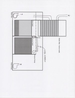
I decided to see if I could convert the existing sump in my 90 gallon tank to operate more like the sytem as described.

I was up against some limitations. First the home-made sump was only 16 inches deep and had a running depth of 12 inches, so I couldn't implement the sand bed exactly as described. Luckily, I had already been running a modified deep sand bed with two sets of stacked trays, each filled with about 1" of fine sand. In the old system, the water was allowed to pass from the bottom up and around each tray in order to maximize contact time.

I removed both sets of trays and installed two modified boxes. The first holds a combination of fine sand (5inches) and course, seperated by the drain sleeve. The second is all course sand / aragonite, (9 inches) for a total of 18 inches. Water flows up through both these sand beds, instead of from the top down.

I installed a main return pump on the left side. This pump runs all the time, returning the water that has been filtered by my home made Roller Mat, to the tank, through a check valve.

The second pump, on the right, is the "œflush" pump. It's basic function is to pull fresh water through the sand bed and return it to the tank. This pump currently runs, at most, 4 min per hour. I will explain how in a second.

Finally there is a process pump on top of the deep sand bed that returns water that has passed through the deep sand bed back to the bottom to start again. Organic carbon is also dosed into the flow path, when necessary, via a BRS 1.1ml/min dosing pump.


Using the Apex, I set up the following logic:

The process pump cycles on for three minutes and rests for two minutes, continuously.

I set two levels of carbon dosing:

Dose 1X (.11 ml, dosed every 5 min)
Dose 3X (.33 ml, doesed every 5 min)

I set three levels of ORP trip points:
ORP Low (ORP readings below -175 mV)
ORP Mid (ORP readings between +58 and -174 mV)
ORP High (ORP readings obove +59 mV)


Finally, four flush cycles:

Cycle 60 Turns on the flush return pump for 15 seconds, every hour.
Cycle 15 Turns on the flush return pump for 10 seconds, every 15 minutes.
Cycle 5 Turns on the flush return pump for 10 seconds, every 5 minutes.
Cycle High Turns on a second, 10 second flush return cycle, every 5 minutes.

The logic is pretty simple:

If the ORP is High, then carbon is dosed at the 3X level every 5 min until the ORP reaches 58mV. Also, the Flush pump is only cycled once per hour during that period. This is the priming phase. The long rest periods are needed start the reaction.

Once the ORP reaches the mid-range, I reduce the dose to the 1X level and increase the Flush cycle to every 15 minutes.

Finally, once the ORP drops below -175mV, I stop dosing carbon and begin to cycle the Flush pump every five minutes. If the ORP continues to drop below -230 mV, I add the second Flush cycle during that 5 min period.

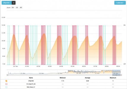
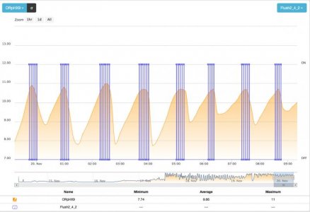
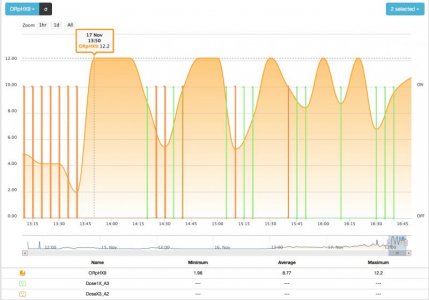
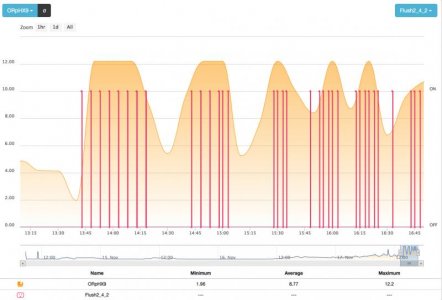
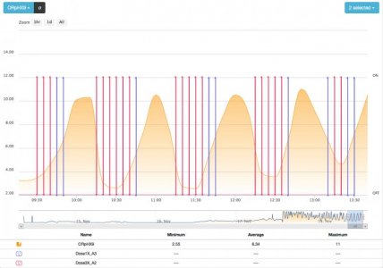
So far, everything seems to be working, as I would have anticipated. The ORP fluctuates from about +50mV to -300mV. I will see if I can tighten this up to stay in a more narrow range but since I really don't know what is the ideal zone, I am not too worried for now.

Aaron
 

Attachments

  • screenshot_12.jpg
    screenshot_12.jpg
    49.8 KB · Views: 4
  • screenshot_13.jpg
    screenshot_13.jpg
    48.7 KB · Views: 8
  • img004.jpg
    img004.jpg
    42.3 KB · Views: 11
Very neat OzIA. I am pretty sure that there are several ways to accomplish the same result as the DyMiCo filter. It will be interesting to see how your implementation does.

The ORP range that an actual DyMiCo filter operates in is from -250mv to +250mv according to their manual. I seem to recall reading somewhere that the filter typically stays between 0mv and -200mv. Actually I think it is further back in this thread. I just looked back, yup MabuyaQ said as much earlier.

I am glad to see you are still experimenting with this type of filtration. The more the merry.

Dennis
 
I updated the program, slightly, this morning at around 9:30.

I added separate trip points for carbon dosing (higher ORP) and also cut the dose in half.

The 3X dose is now 0.165 ml and the 1X dose is 0.073 ml, per dose.
I increased the ORP Low reading to -116 mV from -175 mV.

Carbon is now dosed only when the ORP is zero mV or greater.

I am getting about one cycle per hour. The flow through the filter is about 4gph, so I would turn the tank over about once every 24 hrs. Carbon is being dosed at about 1 ml per hour.

pH in the filter is running at about 7.4. I thought about changing my carbon mix to vinegar to see if the acidity would pull the pH down enough to start breaking down the aragonite. It wouldn't need to come down much to start doing that.

I know it's early but overall, I am pretty pleased with the results. I wish I could tighten the top end up but it continues to cycle all the way up to +260 mV. I have managed to smooth out the bottom, which is now pretty consistently at around -230 mV. I believe if I add a routine that adds a dose as the cycle is starting to go back up from the -230 bottom, instead of waiting till I get past 0 mV, it might smooth out the top as well. This would probably allow me to increase the number of cycles per hour. However, there is something elegant about the nice waveform I am getting so I am a little reluctant to mess with it too much, just yet.
 

Attachments

  • screenshot_16.jpg
    screenshot_16.jpg
    48.8 KB · Views: 10
I would let it run like this for a few weeks and watch your tank closely. What should happen is that the cycle period should speed up and you should start to see multiple cycles per hour. That is of course assuming that your control loop is able to adapt to the increased duty cycle.

As for the PH you are seeing (7.4), I would not worry about lowering it too much at this point. The suggested starting PH in the DyMiCo manual is 7.6, and at 7.4 you are definitely dissolving aragonite. The dissolution rate is probably pretty slow, but it is occurring. As your cycle period goes down, the amount of Alk/Ca being added will increase (if the PH remains at or below 7.6). One of the reasons that the DyMiCo filter is able to supplement at higher than Ca reactor PH's, is due to the size of the aragonite bed involved. Yours will be more modest, but it will still contribute to your supplementation. It will most likely not be enough depending on the demands of your tank, but for light demands, it might be helpful.

I agree that your graph is looking more stable since you have adjusted your control loop.

At 1ml of carbon per hour, that is still a fair bit of carbon per day, depending on the type of carbon you are using, and its strength. I would keep a close eye on the duty cycle and be prepared to back off the amount of carbon dosed to avoid a bacterial bloom event. Ideally you want all the carbon to have been consumed during the cycle and the flush to be returning low nitrate, low carbon water.

Dennis
 
Good advice.

I can control it remotely but I don't have a camera on the tank so I may have to turn it off or put it in bypass, if we leave for the holidays. The carbon is not a full strength vodka sample (10% plus some sugar).

The attenuation has dropped off some since the last post, now between 125 and -125 mV but I am still getting about one cycle per hour. Carbon consumption also decreased to about .75ml per hour. So there appears to be some correlation or balance between the right dose and level of the swings.

I wonder if they are counting the cycles the same way I am? It is very possible that the way I have this set up, is limiting the number of cycles but I am getting throughput that is pretty close to what is described in the manual.

How close are you to getting your system set up?

Aaron
 
Ok, good. So your carbon source is not too potent. That will probably help to minimize the filter from becoming too unstable and running out of control. Speaking of which, you may want to consider adding some safety checks if you have not already. Just to cover off ORP probe failure, etc. Like a maximum amount of carbon that can be dosed per hour and the maximum amount of cycles per hour, etc. This way you can set them conservatively and then increase the limits if you find you are bumping up agaist them. Kind of like a speed limiter on a car :)

My best guess is that they have a control loop that tries to get the filter to cycle at n cycles per hour. In the manual they mention that the return pump will run for a maximum of 16 minutes per hour. Earlier in the thread I calculated the amount of time that the return pump had to run to push out (and pull in) the approximate volume of water that the sand bed layer holds. I think it was 60 secs of on time per cycle. They also mention that the minimum time that the return pump will run per hour is 30 seconds. So if the filter is not yet cycling once per hour, they force a half cycle to keep a reduced amount of water flowing through the filter. At least that is what I am thinking if my calculation is right about the time required to do a full flush (of the sand bed layer).

My best guess is that the carbon dose is tied to the cycle period. Because the carbon is the food source for the bacteria colony in the filter, constraining it too much will limit the colony's growth, and on the opposite side, over supplying carbon will cause unused carbon to be flushed out to the tank. I suspect there is a correlation between the two, keeping the carbon dose balanced to the filter capacity. They also mention that the filter can also reduce DOC (Dissolved Organic Carbon) that is in the water column, which does make sense. That is what we are essentially doing with the carbon dose (adding a very specific DOC that the bacteria can easily assimilate).

If my tank is setup by Christmas I will be happy. The tank is not here yet. I have not been rushing Miracles, the tank builder, because my floor where the tank is going still needs to have some porcelain tiles replaced to account for the larger tank. I have been slowly ordering parts for it though. Today I ordered 132 lbs of Reborn media, 300 lbs of sand along with 400 lbs of Reef Saver Rock. The last thing I need for the filter is another Reef Angel controller.

Dennis
 
Yesterday, I changed the parameters, yet again. The attenuation was decreasing, which may be a good thing but I didn't like the fact that it was starting to work it's way down to zero mV so I started dosing at the bottom of the cycle, instead of the top. Remember, my graph is opposite because it is reading the ORP probe as a pH. (12.2 is equal to -300mV. Zero mV is 7.0 and so on"¦

The latest results are running between -214mV and -116mV. I averaged 4.25 pump cycles per hour. Each cycle equates to about .67 gallons per cycle or just under 3 gallons per hour total, through the system. This is less than I had hoped for but I am also using less carbon, at around .435 ml per hour.

The ORP cycle is still over an hour long. I don't know if there is anything that can be done to adjust it. It doesn't seem to matter where the ORP goes up to, it still takes about the same time to recover back to the -200 mV range. This would seem to indicate that this is the "œfrequency" of the system, similar to a R-C oscillator.

Other than trying to emulate what is known about the DyMiCo system, we really don't know if it is better to have the ORP near zero or -200 mV. A larger sand bed might allow you to operate longer in the lower ranges.

If the attenuation continues to go down, I will increase the size of the flush cycles. This may be something that their system does on it's own as the system breaks in and should get me closer to turning the tank volume over once a day.

Aaron
 

Attachments

  • screenshot_18.jpg
    screenshot_18.jpg
    53.6 KB · Views: 5
  • screenshot_17.jpg
    screenshot_17.jpg
    47.8 KB · Views: 4
Think im unable to see some of the more explanatory build photos. How exactly did you orientate the baffles and how is even flow through the sand beds achieved? Do you have more pics?

Sent from my SM-G903W using Tapatalk
 
Think im unable to see some of the more explanatory build photos. How exactly did you orientate the baffles and how is even flow through the sand beds achieved? Do you have more pics?

Sigh. I always seem to screw up posting photos. I forget that just because I can see them does not mean other people can see them. I went back in looked in a different browser not logged into Google, and yep, no photos. These should show up as I have made a specail thumbnail folder to hold the resized photos.

The filter is disassembled right now while the contractors are "working" on my fishroom, but here are some older photos.

Here are the 2 baffles that will be installed in a 75 gallon tank. The outside pipes in the bottom, the ones with the dog leg made out of 45 degree fittings, really should have been closer to the each edge of the baffle. That is what the dog leg is attempting fix. Unfortunately I can get a hose brush past the dog leg, so they will be replaced with plain straight pipes for final assembly.

j3qcFpRmzG2V5URRAGxRqKZnXebyCRphtYOd8jPJbs7zGb26M_odBu3IZDE4CWKkcyD6iykObQCeUtdkBC_0Gm8lzfk_ANCursjAmT7_fYQe8SYNBCavmzEIxe7xWsOmbWr8TIqhR3rBpqXmUk494uVMRi955WN779u_w-2khf5UgfhqkG7ZSR4t1WmH7jekBjegsGKgzB93bO962AGbpQk0OLo0qzSq2FEpJbYf9NzrQ6Fc18OxVIFk1NF454fxbJx-RlqwI_C48nz6Eed9EzJN38dfxEyMGGHC2Xi1QE3be4ddOW7RM235QFyNOrPuEcjYdvv27qe_IABIA5yNuQYJWZ0kvrgwlsBJ1tR331MbK0iA-i8mBvX7aJlQ4bw6D3DBVDHlQ_uW_kMAJSxMKm1p_duhNy2ITmaTiCCxvV7_7BZdzUHW-YMCHIrQ9TsJqXcTayHG-wcmy54K90qgi2Vqj-tWbcRnIZvvxLVrXZcY2xqe2sIXvfEFjXSRub-uOprpXpr6evhnz414qsUDu33VKo0J7nuQzcq3aFIywrqGsQvdYF1d5t5nGKgOM4Uc608330WwMPT5Ld78HZ5ioLnnBLMX99TctHf3EkSYTdnoEMxs=w747-h1328-no


XmwMJDn89iJwwNlO091EjShwA-iO4qXqkdM1OWclxTu7sVw3vJ98-e819R23TKTd-F75pkahi0LQMmOJXFhY8Fw-OI3a-V5Z2oqYUzFJD5RIvdTNeIy2b-l-x3rRwj0l4afl00VfKuOsV46Ph8lcBH6gLOm3nBlyNLFw_MotJZKUO7XkuNR4w6YYImofJ4GdAHKcS6jtlqUao1wYwtyCjEGBW8r08cgDz-kH2kpG254z9CXoo1qDU6fNz2c9IHx-MT5Gam65gV8aBIr7lZsMkq8atpuqEezQl_yctqFsCxpHEcdx8k6W08FSzCYmDo4XKtZW13D6i0miENgA7HxO1BMgBEKr6Wrxv5P9KhFSi9SH6LRjEUh1fX1Y_DEISMajHP36EwwyiN5fAqq3yoXeX_GdNxLh0e5zT24LqdruVyj6vZI66-1uckEEBHuybyZJWv3VlvuScoOAGiFF-uTCNhPIqZYEU8n0DDiA7gCLCODHj2PDPJmjc16AGUspkUp_iDY_NDGwGe8GwoQiHUenlfavptaBMRjTxGl_y9bgSoXcWp5YfR89_0voKI2gGzyBZs47Z8wGqNgeeV9G2BTjoGCFKEkSkTXYQ26vBGygEutU6YI_=w1328-h747-no


These are the manual flow meters that I ordered in.

HZza1pDCWUaqRiwbmK2_qGqRo63xsQBV9DDQri545522SC7vB-haBjX5x6nZxDo4fBEMKW-HFuTYLzyWXJb36i0_NvtkCzkMqkk6H1Bnlc0Gl8s3jQLtPbmKNHVW3bGNH1sfJWEcXRM0EUS3guAwKn-fV7PJuOJ9muz5bRH7plMyjRzrn_tsEDDDC30UxNFhzKxT7ThZmBLi741eYv42WnkM8mppdFUbw2_lM_-kec37Gng5lBG0JwoB839Ft2fRuujIOy-3YDjGKWxLC6Um0gY7fsRJ0KQL8T3SlM03I6SD9Vr2I3rNPvl8-U6MCQ3OJfz9qJ_TaJ6ebCXyIzzVZnRbRbOC6uQmnik74cfK7kZxL6PSEOGvKcC375w54GaOT9jC3xx38811zMEhHD3hjDK5f8TlCeGW5uLSxjc6Awg-GzoeMc-xfbRqLY92cqE0FkF7ZKfce5X9Kpae4908XCaoI_WLe_ej4_j7moJoEoV6m4a_crs9EkyJf3yrQAXBlUVKJuJmKqNJLl1umsi8VDbGjZCRrMvuxXvu--fnPhI8F3YZw0bA7_sOgvSVPQOodECe_IWGzhefQpZioUF_hOZII9eM-iJBkQXs6YEVsTCuURL1=w747-h1328-no


Sorry I don't have any photos of the filter assembled in the tank when I was test fitting plumbing and pumps. I know I took some but can't seem to find them.

Dennis
 
So, once the baffles are installed, you will pump water into the top two, with the process pump and allow the water to return through the bottom three? If that is the case, shouldn't the top two only be open on one end, the process pump side?

Nice floor.
 
Grrr, still missing 2 photos? How can I fail so badly! :sad2:

Trying a different link ...
k6-mD1R7aM5Vls-irkBhLdheeUWgpahCOatflGDM1xQTIl_Ol1w_wGU61DoZPgWZNrrMk982lywMxNmyJEAL_KD1jLoEo0GIoqquRsBG2PgThAVO-wD9npsORoaEvSqMkHOPXx-3xGMTwrGl7TMPN3AaRsh-elbVuK20BgfFajsMmgUQiU2W13F-mqEfoywwoPGi5B6tnT1nJP7KKw9X_VRnuYFKHvvDdEKpoAexcIpoGulejbzNqRMnxsrwEBEIYBKtoQLRsRnXJJPaTC3Hyqed4PXjWCun0cToDiziwpZgw4t_Eh1y0OcYnMcC9bZg5LMJca4dOIZdxuTW5uawX3G1upoJBFdN4XTkGqSRWOAblU78VZEqZcgSU5n5NjvGf7uC001SvuAtHolaJ6b41slvb_rIpRO_3KyAt0VEElyE46VeDzQkpoLUNln2bW43tcQkXJfeNhhKv_jv3t6kPNw5L9TDv93tahgs79F6JvmJQPehCz9orB6YvHz02CJqa2Cu9afZymnkxeIRi5OsjsdVtv2hhWGuf2OdfrDbPfI2Wg2lfHMvrkr6pXG1wsMSYiecVVZ69NZp_baZK94qLsnlaiWe8C8L2Jv5JoFtB9THx4hV=w1328-h747-no


pd062QWBAIKfU_a8Fd3EnZDvc8fBQhaC95Y6iUAbrsXPP-g_ZkfDfvcterlc0EpfsOZWNfAAdseS5Qg3RebUZvCNoDzKo4kY_jVCnoBWn2HN7nrmCnZ0VexdHF4KdIWjBCPuEJBmgbQZ22-0WHnMgRh_79FTWVtLkABYnZaqpGbmJW5tBvDChXhHogBkNFFHsMQFXACmGx8DN3-eXoh7I42Xc-kwBVlJ1y7mi6ObFaUNOJStRGsMv1B4xAQWf-vpdRermyGa1ZzwCe-2FCYvfdzo76oqdo_tnSV2fL747EbkdKqbmvlvltomT_iR6MOS4IeT-HLIpXtagp6feFJVqEND3CsROo3X5FUYjUZK7mDU0I10FhR7pOpaa5JSgH-ORsogLuAYS5deWtikY43ckEa4BZqhLR5XrKlGQbBgI6vvjjSDvGQJGsrw8-iMb3YxtUMFw8umwsZDnn5u5SRwG9umaGV72iZCkHEsnoDE1K-uAJQ3pTszSthps925MPYFAPjyxj9G_j7rj_h_Hlkdvi59om9ske9ABftfFk64ix-U86zzMy05OxAEVABFK0xxb4COB9I7hbaxMP9tSljJFxjLj7aGfVZR9gvuxLKdNp_g6-m1=w535-h951-no


These are the missing photos from above.

Dennis
 
So, once the baffles are installed, you will pump water into the top two, with the process pump and allow the water to return through the bottom three? If that is the case, shouldn't the top two only be open on one end, the process pump side?

Nice floor.

You are close on the process pump. The pump will pump through the top 2 pipes and the water will flow back to the process chamber through the 2 outside pipes on the bottom row. The center pipe on the bottom will be plugged on the process side and will be used for the return pump to pull water from. I though about keeping the bottom center pipe open on both ends, but decided to plug the process side just to make sure the return pump pulls through the coarse media.

All the bulkheads on the return side will be plugged (except) for the bottom center. The bottom center will be plugged on the process side. I just did not have the plugs yet when I took the photo.

The smaller DyMiCo filter, model 700, only has 3 pipes arranged in a triangle. Top pipe is for the process pump to feed, and the 2 bottom pipes are for the return pump and flow back to the process chamber. Mine is modeled on the 2000.

The floor although nice, is what has delayed everything by several months. Actually the unreliable flooring contractor is the root cause. I hate renovating. Still have about 6 months of renovations to go.

Dennis
 
Looks good thats how i was picturing it as. One thing that still confuses me is how does the "plankton" that this filter boasts to produce so much of actuallymake its way to the display? It mostly lives in the area of water just above the fine sand bed does it not? So then it would have to make its way through the fine sand bed - pvc mesh/cloth - coarse sand bed - through the return pump and come out on the other end alive. (Mine will be an above tank so i will actually pump water to the filter from the sump and it will overflow into the display. Aside from bacterial plankton would this filter not provide less larger zooplankton, pods etc than a regular overhead refugium?

Sent from my SM-G903W using Tapatalk
 
Back
Top