Nutrient Pulse Reactor (DIY DyMiCo filter)

Looks good thats how i was picturing it as. One thing that still confuses me is how does the "plankton" that this filter boasts to produce so much of actually make its way to the display? It mostly lives in the area of water just above the fine sand bed does it not? So then it would have to make its way through the fine sand bed - pvc mesh/cloth - coarse sand bed - through the return pump and come out on the other end alive. (Mine will be an above tank so i will actually pump water to the filter from the sump and it will overflow into the display. Aside from bacterial plankton would this filter not provide less larger zooplankton, pods etc than a regular overhead refugium?

I think the filter mostly contributes bacteria plankton, and larger life forms, like pods, feed on the bacteria and so forth. The other means of contributing to a plankton rich environment is the filter is intended to be operated without a protein skimmer.

I am sure you could arrange a similar structured filter in an overhead arrangement. You would just use an overflow instead of a return pump, ad you would meter the water flowing into the filter instead of out of the filter. In fact the commercial DyMiCo filters use an overhead tank, although they section of part of the actual tank to act as the filter bed. So the filter is not really overhead, it is in the actual tank.

Dennis
 
Just a quick update. I have been experimenting with using iron citrate to lower phosphate on my temporary frag tank. I had mentioned earlier in the thread my plan to potentially use iron citrate with this filter. What I have found is that without sufficient filtration for removing the precipitate, it can still show up on phosphates tests and give incorrect readings. Since the DyMiCo filter is typically not used with protein skimmers, which is how I am filtering the precipitate out in the test tank, then some other filtration will need to be provided capable of exporting the reacted iron phosphate.

You can read the thread on iron citrate here http://www.reefcentral.com/forums/showthread.php?t=2604645

Dennis
 
Back from the holiday…
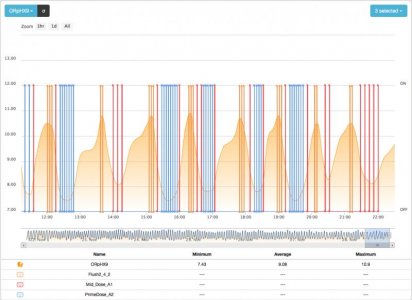
The filter has been up and running for about two weeks now. Before I left, I added a third section of course sand and installed a second ORP probe. I was curious to see if the reaction would continue in that third chamber. Sure enough, the ORP in that area began to drop and leveled out at around -230mV. At that point, I decided I was dosing too much carbon so I cut the high dose, which occurred just before the flush pump was cycled, in half. The ORP in the final chamber rose and leveled out around zero mV. So, I decided to shut that dose cycle off, altogether. The ORP in that final chamber continued to rise up beyond the Apex range as a pH probe (probably around +300 mV. The primary reaction chamber continued to function normally, between 0 and -230 mV, about once an hour, so I believe I have the dose correct (.435 ml / hr).

However, throughput has also dropped to around 50 gallons per day. This may be a function of the size of the filter. The primary reaction chamber is only around 5 gallons of course sand. I am assuming that if it were 10 gallons volume, I would be able to level off closer to turning the tank over once per day. This also lines up with your 10% volume rule. As it is, the Roller Mat, which operates in parallel to the nutrient pulse filter, is running all the time at around 300 gallons per hour so I believe things are being filtered satisfactorily. The skimmer has been off for a month now and phosphate and nitrate readings haven’t changed (0.08 and 0.25 respectively). I was dosing carbon prior to this, just not in this manner. I got a lower PO4 reading yesterday but was unable to confirm it today. I did take today’s reading just after feeding (not very smart) so I may check it again later.

One other noteworthy comment, there is a visual cloudiness to the primary (course) reaction chamber. I am assuming the bacteria population is such that there is a layer of slime on the filter that is diffusing the light. This effect cannot be seen on the fine sand or the third chamber. I am wondering if I should try to flush this out on a monthly basis and then allow the system to restart, just to prevent too much buildup. This would be pretty easy to accomplish by just turning on the flush pump for an hour while turning off the primary return. This would force about 300 gph through all three sand beds.
 
I am not sure I understand your dose timing. Did you say your large carbon dose was timed to occur just before the flush? I am guessing, but I am pretty sure the DyMiCo folks only add carbon once per cycle, and only right after the flush pump stops and the process pump starts.

Dennis
 
1eefcd7b44f5cc2874f22d0d8b823855.jpg


Heres a sketch of the one im planning. It will be above tank so will be fed from a pump in the sump and overflow into display. Last chamber has an airstone and some live rock/rubble to remove methane gas and provide another place for fauna to thrive before making their way into the display. Not set on the dimensions of each section but i am using a 12 x 36 x 18 tank for the filter

Sent from my SM-G903W using Tapatalk
 
Circulating pump line valve is placed outside the filter for easy access since its overhead

Sent from my SM-G903W using Tapatalk
 
1eefcd7b44f5cc2874f22d0d8b823855.jpg


Heres a sketch of the one im planning. It will be above tank so will be fed from a pump in the sump and overflow into display. Last chamber has an airstone and some live rock/rubble to remove methane gas and provide another place for fauna to thrive before making their way into the display. Not set on the dimensions of each section but i am using a 12 x 36 x 18 tank for the filter

Very cool. So your flush pump will be in your main tank (or sump) and will pump water up to the filter which will return through the overflow in the right chamber? What size of tank will this be for? If you can keep the coarse layer 10" thick and have 5" of sand layer, you will be in the ballpark of what the 700 and 2000 filter use. The main difference between the 2 DyMiCo models is the area of the filter, but the depths of the layers are the same.

I like the way that you have the final chamber with an air stone to degass the CO2 before it is returned to the tank. I might have to steal that idea from you. I had been thinking about having my filter return to an above DT holding tank that had an air stone, and having the chamber with the flush pump dry as an emergency overflow, but not having it dry does have some benefits. Like making it easy to remove the flush pump for maintenance without the need for a ball valve to prevent it from filling with water. The use of the stand pipe in the flush chamber would allow for this.

Dennis
 
I like the top down approach Dan. Will you be using glass or acrylic? If you have the option, I would make it deeper. The flow through the fine sand is pretty low, as I found out the other day so you may need to account for a 3 to 4 inch height differential between the overflow and the main filter area.

Dennis, the Apex program I have set up is based on 4-minute intervals, using the "œoscillate" program. This turns an outlet or virtual outlet, either on/off/on or off/on/off, based on time. The Apex logic is fairly rudimentary and this seemed like the best way to emulate the activity of the DyMiCo cycles.

The process pump comes on for one minute and then rests for 1.5 minutes then runs again for another 1.5 minutes. Since there is only a four minute loop, the two run cycles end up being back to back, so 2.5 minutes on and 1.5 minutes off in reality but the key is when it runs during the four minute cycle.

There are three set points or "virtual outlets" in Apex speak. These are simple on / off markers, again using time-based logic coupled with decisions based the value of the ORP. I am not aware of any way to change the way the Apex operates based on the direction the ORP value is moving so this was my solution.

ORP High: If the ORP value is less than 0 mV, this outlet is "on".
ORP Mid: If the ORP value is between zero and -116 mV then this outlet is "œon".
ORP Low: if the ORP value is below -116 mv then this outlet is "œon".

Now I make dosing decisions based on the status of these outlets. I had three of them but I turned off the one called "Hi Dose". Again, these happen every 4 minutes. Well, actually, I had some of these set on 8 minute cycles but changed the Prime cycle to 4 minutes today. Also, I have changed some of the logic and set points over these past few weeks, so some of the steps are redundant and unnecessary.

Prime Dose: Turn on the BRS dosing pump for three seconds, every four minutes, unless the ORP value is greater than -58 mV, then this outlet never turns on.

Mid Dose: Turn on the BRS dosing pump for three seconds, every 8 minutes, unless the ORP High or ORP Low outlets are on.

Hi Dose: Turn on the BRS dosing pump for two seconds unless the ORP is greater than -200 mv. This dosing cycle is no longer used. The actual outlet that drives the BRS pump is a slave to each of these virtual outlets. If any of them go "œon" then the dosing pump outlet turns on.

Finally, I will turn on the flush pump for 12 seconds if the ORP is less than -200 mV. This cycle is timed to wait one minute for the process pump to go into its rest period.

These outlets allow me to see when each of them is activated in comparison to the ORP reading. Basically the dosing pump is trying to come on at the beginning of every cycle but will look at the status of the ORP outlets before doing so. The flush pump tries to do the same thing, one minute into the cycle, unless conditions prevent it. The outcome is that the ORP is fluctuating from -215 to 0mV and the flush pump is coming on when the ORP reaches the low peak. When the fresh water comes in and ORP starts to head toward zero, the flush pump stops cycling and carbon starts to be dosed, in small amounts every four minutes, until the ORP drops down to -200 mV and the process starts again. The process is dynamic, as you can see.

I am not using the filter to provide the calcium and carbonate, that is provided by a CaOH dosing system, which also maintains the water level. The primary reason for trying to implement this is for increased bacteria and nitrate / phosphate reduction.

Aaron
 

Attachments

The more I think about the stand pipe in the third chamber that Dan is planning on using the more I like it. This would serve a lot of purposes. The DyMiCo filter uses a flush pump On cycle with a preset time period. That is why the flow rate of the flush pump has to be manually set using the ball valve and monitored using and flow meter. They are essentially using the on period at a given flow rate to return a calculated volume of water from the DT to the filter. Using Dan's stand pipe would allow the volume of the third chamber to be used as the measurement of the volume of water to return to the DT. Level sensors could be employed to control when the desired amount of volume has been returned and to the DT and end the flush cycle. Both a high level and low level sensor could be employed and the amount of time it takes for the flush pump to trigger the low sensor could be used to signal a fault condition (E.g. period too long means flush pump needs cleaning). The internal volume of the flush chamber would become important, but the height of the level sensors could be adjustable to provide a bit of leeway.

The same setup could be employed in the process chamber. Two level sensors mounted close to the same level as each other. The top one would be expected to trigger very quickly after the process pump turns on and failure to do so would signal the process pump needs cleaning. The lower sensors tripping would signal the water is not returning to the process chamber and that the return pipes need cleaning.

Having the ability to electronically monitor the functioning of the pumps would be a great improvement over having to visually monitor them as suggested in the manual.

Dennis
 
Maybe I am mis-understanding the flow path for Dan's design. Isn't that stand pipe in the third chamber, just to redirect the water to the bottom but primarily to prevent water from entering the third chamber, unless the level in the primary filter area goes up? It looks to me like the loop is above the gravity return to the tank.
 
Maybe I am mis-understanding the flow path for Dan's design. Isn't that stand pipe in the third chamber, just to redirect the water to the bottom but primarily to prevent water from entering the third chamber, unless the level in the primary filter area goes up? It looks to me like the loop is above the gravity return to the tank.

My understanding, and Dan can correct me if I am wrong, is that the stand pipe in the third allows the water level to be independent of the rest of the filter chambers. He is also directing the incoming water to the bottom of the chamber, and overflowing from the top drain.

The height of the stand pipe will also control the water level in the other 2 chambers as the return to the tank is lower than the highest point on the stand pipe.

I don't believe Dan is going to be using the water height (in the filter) to control any ATO function. If I incorporate a similar design for the return chamber, except with a return pump instead of an overflow drain, I will need to include an ATO capability.

Dennis
 
I like the top down approach Dan. Will you be using glass or acrylic? If you have the option, I would make it deeper. The flow through the fine sand is pretty low, as I found out the other day so you may need to account for a 3 to 4 inch height differential between the overflow and the main filter area.

Dennis, the Apex program I have set up is based on 4-minute intervals, using the "œoscillate" program. This turns an outlet or virtual outlet, either on/off/on or off/on/off, based on time. The Apex logic is fairly rudimentary and this seemed like the best way to emulate the activity of the DyMiCo cycles.

The process pump comes on for one minute and then rests for 1.5 minutes then runs again for another 1.5 minutes. Since there is only a four minute loop, the two run cycles end up being back to back, so 2.5 minutes on and 1.5 minutes off in reality but the key is when it runs during the four minute cycle.

There are three set points or "virtual outlets" in Apex speak. These are simple on / off markers, again using time-based logic coupled with decisions based the value of the ORP. I am not aware of any way to change the way the Apex operates based on the direction the ORP value is moving so this was my solution.

ORP High: If the ORP value is less than 0 mV, this outlet is "on".
ORP Mid: If the ORP value is between zero and -116 mV then this outlet is "œon".
ORP Low: if the ORP value is below -116 mv then this outlet is "œon".

Now I make dosing decisions based on the status of these outlets. I had three of them but I turned off the one called "Hi Dose". Again, these happen every 4 minutes. Well, actually, I had some of these set on 8 minute cycles but changed the Prime cycle to 4 minutes today. Also, I have changed some of the logic and set points over these past few weeks, so some of the steps are redundant and unnecessary.

Prime Dose: Turn on the BRS dosing pump for three seconds, every four minutes, unless the ORP value is greater than -58 mV, then this outlet never turns on.

Mid Dose: Turn on the BRS dosing pump for three seconds, every 8 minutes, unless the ORP High or ORP Low outlets are on.

Hi Dose: Turn on the BRS dosing pump for two seconds unless the ORP is greater than -200 mv. This dosing cycle is no longer used. The actual outlet that drives the BRS pump is a slave to each of these virtual outlets. If any of them go "œon" then the dosing pump outlet turns on.

Finally, I will turn on the flush pump for 12 seconds if the ORP is less than -200 mV. This cycle is timed to wait one minute for the process pump to go into its rest period.

These outlets allow me to see when each of them is activated in comparison to the ORP reading. Basically the dosing pump is trying to come on at the beginning of every cycle but will look at the status of the ORP outlets before doing so. The flush pump tries to do the same thing, one minute into the cycle, unless conditions prevent it. The outcome is that the ORP is fluctuating from -215 to 0mV and the flush pump is coming on when the ORP reaches the low peak. When the fresh water comes in and ORP starts to head toward zero, the flush pump stops cycling and carbon starts to be dosed, in small amounts every four minutes, until the ORP drops down to -200 mV and the process starts again. The process is dynamic, as you can see.

I am not using the filter to provide the calcium and carbonate, that is provided by a CaOH dosing system, which also maintains the water level. The primary reason for trying to implement this is for increased bacteria and nitrate / phosphate reduction.

Aaron
Good to know ill make my overflow and stand pipe maybe 4" lower to account for that. Glass. I think it would be hard to fit it in its space if i made it taller pluss then id have to have the tank custom built the size im using is a standard 30g breeder.

Sent from my SM-G903W using Tapatalk
 
Last edited:
Maybe I am mis-understanding the flow path for Dan's design. Isn't that stand pipe in the third chamber, just to redirect the water to the bottom but primarily to prevent water from entering the third chamber, unless the level in the primary filter area goes up? It looks to me like the loop is above the gravity return to the tank.
Exactly. The water level in the 3rd chamber will always be just below the over flow and the water in the filter bed SHOULD be always level with the rim of the stand pipe, but apparently it needs to be a bit lower? Fortunately i can always make new stand pipes until i find the sweet spot ill just make sure not to glue it into the bulkhead until i do..or just use a union

Sent from my SM-G903W using Tapatalk
 
Eventually the water has to work it's way back to the third chamber or you would have nothing to pump or drain.
 
I wouldn't glue it anyway. I never glue any pipe that is contained within (can't leak to the outside). That way you can always make adjustments or take it out if you need to.
 
My understanding, and Dan can correct me if I am wrong, is that the stand pipe in the third allows the water level to be independent of the rest of the filter chambers. He is also directing the incoming water to the bottom of the chamber, and overflowing from the top drain.

The height of the stand pipe will also control the water level in the other 2 chambers as the return to the tank is lower than the highest point on the stand pipe.

I don't believe Dan is going to be using the water height (in the filter) to control any ATO function. If I incorporate a similar design for the return chamber, except with a return pump instead of an overflow drain, I will need to include an ATO capability.

Dennis
Thats right

Sent from my SM-G903W using Tapatalk
 
Eventually the water has to work it's way back to the third chamber or you would have nothing to pump or drain.
Not sure i follow your point. It overflows into the erd chamber from the stand pump when water is pumped into filter

Sent from my SM-G903W using Tapatalk
 
Sorry, maybe we are saying the same thing. The only difference between the two applications:

Your top down method will mean that water in the main (center) chamber comes up first, as there will need to be some height differential before water moves through the sand over the stand-pipe and into the third chamber.

For Dennis, the effect would be just the opposite. Water in the third chamber would fall quickly unit water worked it's way back to the center chamber from the aquarium, through the sand and over the stand-pipe to refill the third chamber.
 
I think we have our first 2 variations on the design. Mine would be a traditional under the tank, bottom up filter. While Dan's is an over the tank, top down design :)

Dennis
 
Back
Top