dingodan87
New member
I see
Sent from my SM-G903W using Tapatalk
Sent from my SM-G903W using Tapatalk
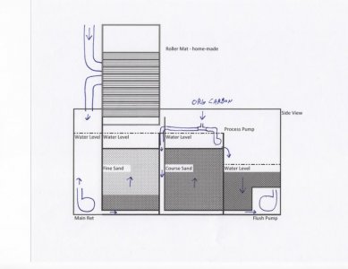
Just got what you meant with the water level difference ozia. You mean i need to have the water level in the filter bed and the stand pipe 3 " from the rim of the filter or it will overflow. I am setting the baffles so the middle chamber will overflow into the 3rd chamber before overflowing over the rim of filter. Are you using the same flush pump as dymico uses? Is that typical with their systems as well?
I like the top down approach Dan. Will you be using glass or acrylic? If you have the option, I would make it deeper. The flow through the fine sand is pretty low, as I found out the other day so you may need to account for a 3 to 4 inch height differential between the overflow and the main filter area.
Dennis, the Apex program I have set up is based on 4-minute intervals, using the "œoscillate" program. This turns an outlet or virtual outlet, either on/off/on or off/on/off, based on time. The Apex logic is fairly rudimentary and this seemed like the best way to emulate the activity of the DyMiCo cycles.
The process pump comes on for one minute and then rests for 1.5 minutes then runs again for another 1.5 minutes. Since there is only a four minute loop, the two run cycles end up being back to back, so 2.5 minutes on and 1.5 minutes off in reality but the key is when it runs during the four minute cycle.
There are three set points or "virtual outlets" in Apex speak. These are simple on / off markers, again using time-based logic coupled with decisions based the value of the ORP. I am not aware of any way to change the way the Apex operates based on the direction the ORP value is moving so this was my solution.
ORP High: If the ORP value is less than 0 mV, this outlet is "on".
ORP Mid: If the ORP value is between zero and -116 mV then this outlet is "œon".
ORP Low: if the ORP value is below -116 mv then this outlet is "œon".
Now I make dosing decisions based on the status of these outlets. I had three of them but I turned off the one called "Hi Dose". Again, these happen every 4 minutes. Well, actually, I had some of these set on 8 minute cycles but changed the Prime cycle to 4 minutes today. Also, I have changed some of the logic and set points over these past few weeks, so some of the steps are redundant and unnecessary.
Prime Dose: Turn on the BRS dosing pump for three seconds, every four minutes, unless the ORP value is greater than -58 mV, then this outlet never turns on.
Mid Dose: Turn on the BRS dosing pump for three seconds, every 8 minutes, unless the ORP High or ORP Low outlets are on.
Hi Dose: Turn on the BRS dosing pump for two seconds unless the ORP is greater than -200 mv. This dosing cycle is no longer used. The actual outlet that drives the BRS pump is a slave to each of these virtual outlets. If any of them go "œon" then the dosing pump outlet turns on.
Finally, I will turn on the flush pump for 12 seconds if the ORP is less than -200 mV. This cycle is timed to wait one minute for the process pump to go into its rest period.
These outlets allow me to see when each of them is activated in comparison to the ORP reading. Basically the dosing pump is trying to come on at the beginning of every cycle but will look at the status of the ORP outlets before doing so. The flush pump tries to do the same thing, one minute into the cycle, unless conditions prevent it. The outcome is that the ORP is fluctuating from -215 to 0mV and the flush pump is coming on when the ORP reaches the low peak. When the fresh water comes in and ORP starts to head toward zero, the flush pump stops cycling and carbon starts to be dosed, in small amounts every four minutes, until the ORP drops down to -200 mV and the process starts again. The process is dynamic, as you can see.
I am not using the filter to provide the calcium and carbonate, that is provided by a CaOH dosing system, which also maintains the water level. The primary reason for trying to implement this is for increased bacteria and nitrate / phosphate reduction.
Aaron
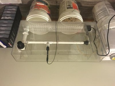
Lol. Sweet! How did you plumb your probe directly to your piping? I was trying to think of a similar idea allowing the probe to be removed from the side of the tank through a bulkhead since itll be hard for me to get the probe in and out for cleaningCheck it out. I am going to set this one up on my other tank. I'm calling it the DingoDown version.
28 X 17 X 6 (internal dimensions) It will be a gravity return unit. I have about 8" behind this tank and it has a black panel so it won't be visible.
There is no third compartment, just the return box. It's made of poly carbonate. I coopted the stand-pipe idea from Dan. I'm using pvc compression drain fittings so I can remove or move the final piece of pipe to adjust the water level.
I will probably order some media tomorrow and see if I can get this one going soon.
Aaron