Pete's 110 build

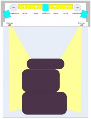
sorry forgot the light diagram

and there is an end view of the tank in this video with all light on at about 1:05
<object width="853" height="505"><param name="movie" value="http://www.youtube.com/v/si_xKTi1MPc?fs=1&hl=en_US&rel=0&hd=1"></param><param name="allowFullScreen" value="true"></param><param name="allowscriptaccess" value="always"></param><embed src="http://www.youtube.com/v/si_xKTi1MPc?fs=1&hl=en_US&rel=0&hd=1" type="application/x-shockwave-flash" allowscriptaccess="always" allowfullscreen="true" width="853" height="505"></embed></object>
 

Attachments

  • lights%20w%20led.jpg
    lights%20w%20led.jpg
    28 KB · Views: 22
Last edited:
I should have a busy weekend coming up as I plan to hook up the Ca reactor and I just bought a bunch of parts to install the 24 Cree XR-E Royal Blue LEDs as suplimental lighting to provide; shimer, more light on the side of the rock faces and more coral color pop.

Plus I'm suipose to get with a guy to pick up some stuff from my old 300g

the LED's will be installed on a dimmable controler that I hope to hook up to a RKE or other controler upgrade in the future

parts ordered (they better all show up before this weekend)
24) Cree XR-E LED's
24) 60 deg optic lens
1) Meanwell ELN 68-40D dimable driver
24) 1.5" x 1.5" x 0.5" heatsinks
themal epoxy

parts I still need to pick up this weekend local
1.5" x 1.5" aluminum angle for strip light frames
2) 1amp fuses
misc mounting hadware

it will be my first time using LED's so it should be a fun build
 
Looking forward to seeing how it turns out! Make sure you put up a diagram or picture of how you parallel the LEDs.
 
Looking forward to seeing how it turns out! Make sure you put up a diagram or picture of how you parallel the LEDs.

here is a sketch of the intended LED mounting to a 46" long piece of alumium angle - I may still add a side splash guard.
file.php


and here is the wiring diagram, only difference is I'll add fuses to the power leads to the LED's
file.php
 
I got home late tonight and was happy to see all the LED parts came in
file.php


heatsink
file.php


led with optic and heat sink
file.php


as you can see the heat sink comes with a white thermal tape but I don't think I'll use it. I'll be using the themal epoxy instead

I'll need to run to the hardware store to pick up the aluminim stock angle iron, 18 gage wire, solder etc. I'll still need to get some final dimentions before starting to cut the aluminum mounts and start the assembly
 
What amperage are you going to run the LEDs at? Assuming that you can adjust that Meanwell if you pop it open.
 
What amperage are you going to run the LEDs at? Assuming that you can adjust that Meanwell if you pop it open.

If I'm reading everything right 1 amp is max for each string of 12

The meanwell 1s maxx 1.3 amps and is adjustable by a pot inside that is fairly easy to get to. When setting LED strings it is recomended to lower the output by adjusting the pot full down and bring it up to an optimal setting using a volt ohms meter. This is a required step when you have a driver that exceeds the maximum.

By splitting I should only get max of 650mA per string and according to the place I bought them from that's very close to the optimal setting for 12 of the XRE's, so technically I could skip the step, but, I'll still test it at the lower setting and bring them up to confirm everything.
 
Last edited:
Thats one thing I was going to suggest, if you run both stings at 500mA (1000mA total on the driver) then even if one LED shorted and shunted all the power into one string you would still be right at the maximum for the XR-Es.
 
Thats one thing I was going to suggest, if you run both stings at 500mA (1000mA total on the driver) then even if one LED shorted and shunted all the power into one string you would still be right at the maximum for the XR-Es.

Thanks Alex - I'll work it toward that goal
I should have al the soldering done tonight and I'll work on the assembly tomorrow and should be ready to test and set the amperage but will need to read up on the proper technique first
 
here is some progress

after measurements the front LED strip can't be longer then 42" due to hood opening clearance
So the math for the front side works like this
- 12 LED's = 11 spaces @ 3 5/8" on center = 39 7/8"
- add in the 1 1/2" width of a heatsink and I'm at 41 3/8"
- this leaves me with 5/8" clearance and for a mounting clip

the back side can be 46" and will be spaced at 4"
- 12 LED's = 11 spaces @ 4" = 44"
- plus heatsink = 45 1/2"

After measurements I needed to tin the heatsinks - basically this is adding some lead free solder to the contact area on the LED
file.php


file.php
 
Last edited:
I've been working on the LED's on and off through the day but should probably rough out how much time this build takes so people can gauge if it's worth it for them to undertake.

At this point the usual approach would be to mount the LED's to a large heat sink or what ever is used for the final mounting. Since my LED's will be mounted to a piece of aluminum angle to act as a splash shield it makes it very difficult to solder the wires on as they would be partially concealed. I decided to use the heat sink tape as a temporary mount and located the LED's and heat sinks on the aluminum angle at the proper spacing and proceeded to cut the wires to the appropriate length and soldered them in place.

Next step will be to repeat the process for the back 46" strip and then start on the Aluminum angle drilling and assembly.

here I'm cutting the wires to lenght
file.php


wires soldered in place for the front 42" light strip
file.php


close up of LED solder
file.php
 
After setting the driver POT to it's lowest setting and making the last few connections for the plug, hooking up the driver, placing a volt ohms meter in line and hooking up the DC dimmer control (without the DC control the unit is off) I proceeded to test the lights. At first nothing but I knew I was tanking a 50/50 chance on the DC control polarity, once reversed, presto nice blue lights.

Then I smelt something burning, like melted solder. At first thought it was a connection, I made, then the lights dimmed and I thought oh nooo, there goes the driver or the lights. The I saw smoke coming from my 30+ year old volt ohms meter that only measured up to 250mA DC, so much for that old piece of equipment I should have known better as the amperage I was wanting to set was around 500mA. Thinking with the Pot at the lowest setting I figured it could handle it. Max setting with the parallel sets of 12 (24 total) should be 650. So I removed the volt ohms meter and the lights were bright again.

I proceeded to dial up the POT to maximum setting at 650mA, with maximum the LED's are rated for being is 1A (1,000mA) and all LED lit I figured that without the volt ohms meter I had enough safety margin. I dialed back (counter clockwise on the POT) the LED's to see where they started to dim then turned it back up just a tad as visually it appeared to be optimal (light to voltage ratio). Next I did a quick check of the dimmer by resetting the DC transformer to a lower voltage and all worked fine. Next step is cutting and drilling the aluminum and mounting the LED's

Driver POT ohms adjustment
file.php


lights with Pot at lowest setting
file.php


POT at about 75% (visually just as bright as 100%)
file.php
 
IS this with both strings running or just one string? Also, did you bin your LEDs for their Vf's? I ask because even LEDs among the same brand/color have different Vf's and ifone string happened to get a combination that had a total voltage drop higher then the other string it would suck more amperage to that string. It should be really easy to test if your two strings are running within 10% of each others amperage, but you would definitely need a multimeter that goes up to 10A ;) .
 
IS this with both strings running or just one string? Also, did you bin your LEDs for their Vf's? I ask because even LEDs among the same brand/color have different Vf's and if one string happened to get a combination that had a total voltage drop higher then the other string it would suck more amperage to that string. It should be really easy to test if your two strings are running within 10% of each others amperage, but you would definitely need a multimeter that goes up to 10A ;) .

both strings were running durring the test

they are all the same Bin #D316

I'll probably make a run to FRY's later today to pick up another multimeter along with a couple other things
 
I should have clarified what I meant by binning. The factory bins all of their LEDs so that they are producing a certain range of wavelengths (i.e. 450nm +/- 10nm). What they don't do is bin the forward voltage (Vf) needed to run the LED. The Vf depends on your current and is normally around 3.5V, I think, but each individual LED of the same manufacturers Bin might change a little. Say, 3.4-3.6V. Since Voltage in series is additive a 0.1V increase on a single LED can add up to a big change in total voltage between strings ran in parallel, causing the string with the higher cumulative forward voltage to suck more of the amperage produced by the constant current power supply.

Fixing this is very simple though. First, using a volt meter check the voltage drop across the ENTIRE 1st string and compare it to the entire second string. If they are within 10% of each other you are probably good to go. If not, then check the individual Vf's of each LED in your array by measuring voltage drop from the + pad to the - pad on a single star. Then take your highest Vf LED from your highest voltage string and swap it with the lowest Vf LED on your lower voltage string. This should fix the problem.

None of this is life threatening (LED threatening?), but if you don't do this there is a chance one of your strings will run at a higher amperage, run hotter, and produce more light then the other string, which might or might not matter in your overall setup.
 
excelent point Brett, I would have never thought about that. Is there a way to check the strings with everything online?

I have everything mounted - now I just need a hand getting the canopy back on
file.php
 
this dendro has always been great looking but always just orange, now with the royal blue LED's it shows a little lavender
file.php
 
some zoas under the new royal blues
<object width="853" height="505"><param name="movie" value="http://www.youtube.com/v/y23xU96BINE?fs=1&hl=en_US&rel=0&hd=1"></param><param name="allowFullScreen" value="true"></param><param name="allowscriptaccess" value="always"></param><embed src="http://www.youtube.com/v/y23xU96BINE?fs=1&hl=en_US&rel=0&hd=1" type="application/x-shockwave-flash" allowscriptaccess="always" allowfullscreen="true" width="853" height="505"></embed></object>
 
Wow Pete looking good. Sorry about your old tank. I have been wondering what happen with your thread. Traveling a lot lately myself. Can't wait to see your progress ...Thoes LED's are sweet
 
Wow Pete looking good. Sorry about your old tank. I have been wondering what happen with your thread. Traveling a lot lately myself. Can't wait to see your progress ...Thoes LED's are sweet

thanks Eric

here is a vid showning most of the corals
<object width="853" height="505"><param name="movie" value="http://www.youtube.com/v/NiX0Ll39jMg?fs=1&hl=en_US&rel=0&hd=1"></param><param name="allowFullScreen" value="true"></param><param name="allowscriptaccess" value="always"></param><embed src="http://www.youtube.com/v/NiX0Ll39jMg?fs=1&hl=en_US&rel=0&hd=1" type="application/x-shockwave-flash" allowscriptaccess="always" allowfullscreen="true" width="853" height="505"></embed></object>
 
Back
Top