So I went to install a GFCI outlet and found...

Lion-o

Member
*Disclaimer* I am no good with the camera. The household camerawoman is away for the weekend :)

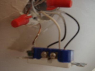
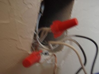
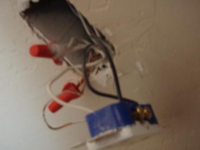
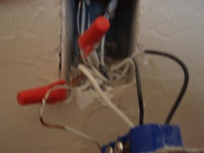
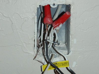
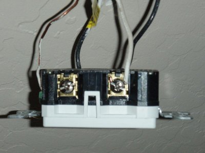
Essentially, the 2 white wires that I would expect to be plugged into the outlet are instead wrapped up and capped off with a 3rd white wire which only plugs into the outlet once.

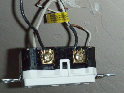
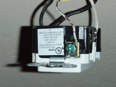
The black side however has two black wires plugged in. I'm not an electrician, nor do I claim to know anything about it. But I did do some circuitry stuff (Computer science) in college and I read the instructions, and this is not what I was expecting to see (either two whites/blacks or one white/black). It looks like a lazy hack job... but since I have no clue - does anybody know why they would have done it this way? Is this a common occurrence? Can I just remove the cap, separate the 2 white wires and use them the expected way in my GFCI outlet?

thanks in advance!
danny
 

Attachments

  • P7271751.jpg
    P7271751.jpg
    10.5 KB · Views: 4
  • P7271752.jpg
    P7271752.jpg
    12.4 KB · Views: 7
  • P7271753.jpg
    P7271753.jpg
    11.9 KB · Views: 4
  • P7271754.jpg
    P7271754.jpg
    12.3 KB · Views: 7
Another circuit is tied to that outlet. It looks like they used the outlet to connect two wires instead of a third wire nut. Turn off the circuit, disconnect the plug and verify which two wires are together ( use ohmmeter on back of outlet to see which holes are electrically connected, should be the black wires). I have seen outlets wired like that many times.
 
Do you have an multimeter? this is your best way of figuring this out...otherwise just get an electrician to come by.
 
Another circuit is tied to that outlet. It looks like they used the outlet to connect two wires instead of a third wire nut. Turn off the circuit, disconnect the plug and verify which two wires are together ( use ohmmeter on back of outlet to see which holes are electrically connected, should be the black wires). I have seen outlets wired like that many times.

+1
One of the black wires is 'Hot' from the circuit breaker, the other runs to the next outlet down the line. You need to figure out which is which. If you don't have a multimeter, you can turn off the power, disconnect one of the wires and cover it with a wire nut or electrical tape, then turn on the power again. If the outlet still has power, the one that's connected is the hot one and the other is the traveler. If there's no power, it's the reverse.

You should also figure out were the traveler goes. If it's the next outlet on the wall, figure out whether you want it to be GFI protected or not before you install the outlet.
 
Another circuit is tied to that outlet. It looks like they used the outlet to connect two wires instead of a third wire nut. Turn off the circuit, disconnect the plug and verify which two wires are together ( use ohmmeter on back of outlet to see which holes are electrically connected, should be the black wires). I have seen outlets wired like that many times.

+2 I'm not an electrician, but I have wired/rewired a couple houses now and that is exactly what you should find. In Ohio, even if it is just going to the one outlet, you are still supposed to use short tails and wire nuts to connect to the main line.
 
Is the switch back switched? As in does a switch on the wall control the top outlet? If so that is not a neutral but a hot wire that wasn't properly labeled.
 
Not sure why they pig tailed the neutrals together, but you can just put both black and both white wires on the line side of the gfci and be good to go.
 
Im an electrician and although our rules are slightly different here in Ontario they aren't that far off. I am having a hard time seeing all the wires in the box but one good reason why they may have done this is a shared neutral between two circuits. It will work fine at that outlet. Ive never tried wiring one up this way but I would have to assume anything down the line would be equally as well protected as long as the line and load are in the right spots on the receptacle. one easy way to see if this is the case (assuming it was wired correctly) is to turn the gfci over see if it says line and load follow the line back to where the wires enter the box. if that cable just has a black and white ignore what ive said if there are three (black red white) its a shared neutral
 
I am an electrician.

They bring the tail out of the splice for the neutral because the wirenut is valid much more reliable connection. It reduces the chance of having a break in the neutral which could be very dangerous.
A break in the hot doesn't matter as much as the downstream devices just wouldn't work. And you can only have so many wires and wire nuts in the box.


I like seeing the neutral with the tail personally. You can put the tail into the gfi just fine. Or you can remove the wire nut and install the 'normal' way. Just make sure you know what wires are line and load that way.
 
Thanks for all the replies :) Some differing opinions - but if I simply install the gfci outlet in the same manner as what is already in there, I should be good to go?

I know the double wires mean there are additional outlets downstream, but really I don't care if anything else gets protected or not. Also, this outlet is not controlled by a light switch.

-danny
 
You have an outlet or another socket on it. The whites should be your neutrals, the blacks your live, and your third solo is the ground. You should be able to piggy tail it right in. but I am a chimney guy, ex chef.
 
Thanks for all the replies :) Some differing opinions - but if I simply install the gfci outlet in the same manner as what is already in there, I should be good to go?

I know the double wires mean there are additional outlets downstream, but really I don't care if anything else gets protected or not. Also, this outlet is not controlled by a light switch.

-danny

Yes you could simply install the way the old one was.

The reason you don't want the downstream devices protected is because it increases the risk of a trip.
 
Put the wires on the line side. Back of the recp. should be mark line and load. Line should be the bottom ones. Just put your wires under the line side. Thats way just that recp. is protected. If you need help. PM me your number and I will walk you though it.
 
Put the wires on the line side. Back of the recp. should be mark line and load. Line should be the bottom ones. Just put your wires under the line side. Thats way just that recp. is protected. If you need help. PM me your number and I will walk you though it.

Load side generally has a sticker over it.

The instructions are pretty clear.
 
yup all the last advice is pretty much bang on if you don't want anything else protected turn the breaker off take the two black wires out make a joint with a tail like the whites and put the tail on the bottom of the gfci like the white and only that outlet will trip and nothing down the line will trip it either
 
Hi again,

I had some time this evening so I went to work on this guy, installing the new GFCI to replace the old outlet. I rewired exactly the same as it was before. The two line wires on top (neutral white, black hot) and the one load wire on the bottom (hot black). I took the sticker off the new GFCI device and wrapped it around the bottom black to make sure I did not mix them up. Of course, the ground wire is wrapped into the bottom ground slot.

Turned the power back on and tested it. LED indicator was coming on for the plug but my lamp was not working. Tried test/reset buttons, per instructions - no dice.

Turned power back off, removed and reconnect everything the same. Retried - this time, still no lamp power but this time no LED indicator either :confused:

Tried a third time, this time cleaning and connecting a few more wires. This felt the best as I put it back in but when I tested, still no Lamp power or LED indicator going on for the outlet.

Any ideas? Is it possible the blacks were flipped originally? I havent had any issues with this outlet or the others in the past. And, all the other outlets in my room are still working - so I'm not sure what is downstream of this one!!

I'm thinking I'll try and call an electrician/handyman over if I can get one soon, but very frustrated that I have to do that since it seems so simple.. I don't get what's wrong!

thanks,
danny
 

Attachments

  • P7301758.jpg
    P7301758.jpg
    52.2 KB · Views: 5
  • P7301760.jpg
    P7301760.jpg
    58.7 KB · Views: 3
  • P7301763.jpg
    P7301763.jpg
    45.7 KB · Views: 4
  • P7301764.jpg
    P7301764.jpg
    50.4 KB · Views: 6
Why not buy a multimeter or cheap power probe to see which one is the hot line? That is a tool you should have in your toolbox anyway.
 
Back
Top