Use PWM to control your Jebao DCT pump using brushless motor controller from ebay

I have a dct4000.
I run it on one led with valve wide open to get the same flow as eheim 1262 with valve slightly closed. That's like 15w vs 65w.
I run it now at 3 leds so water level on DT is slightly higher to get a higher turnover rate.
 
Wow. I run 3 DCT15000 on 10 LEDs to get to 9000 GPH but I need to modulate this over time or risk killing my SPS. I've already had coral death since disengaging my mechanical flow alternator.

<a href="http://s1062.photobucket.com/user/karimwassef/media/16B4E07C-EEB8-4E97-AF6D-D3569D9281E0_zpsc92yqwxs.jpg.html" target="_blank"><img src="http://i1062.photobucket.com/albums/t496/karimwassef/16B4E07C-EEB8-4E97-AF6D-D3569D9281E0_zpsc92yqwxs.jpg" border="0" alt=" photo 16B4E07C-EEB8-4E97-AF6D-D3569D9281E0_zpsc92yqwxs.jpg"/></a>

That's why I've been pushing for a solution. I'm going to move forward with the lower flow green boards temporarily to avoid more death to the vulnerable sections of the reef.
 
Karim, are you using the pump as return or as closed loop?


parts arrived today.
I will need to pull out my dct pump (probably this weekend) from the sump so I can use it for this project.
I will start with the open loop code and see if I can make the motor turn step by step.
 
I have two pumps in my sump. Each outlet on one end of the tank. The intent is to alternate a sinusoidal flow using the Apex:

<a href="http://s1062.photobucket.com/user/karimwassef/media/55_zpsr2nbcwwh.png.html" target="_blank"><img src="http://i1062.photobucket.com/albums/t496/karimwassef/55_zpsr2nbcwwh.png" border="0" alt=" photo 55_zpsr2nbcwwh.png"/></a>

I have been following this thread with the same goal in mind... currently I'm using gyre pumps to achieve this, but would much rather have the bulk movement from my return, with the smaller pumps creating the pulses and non laminar flow.
 
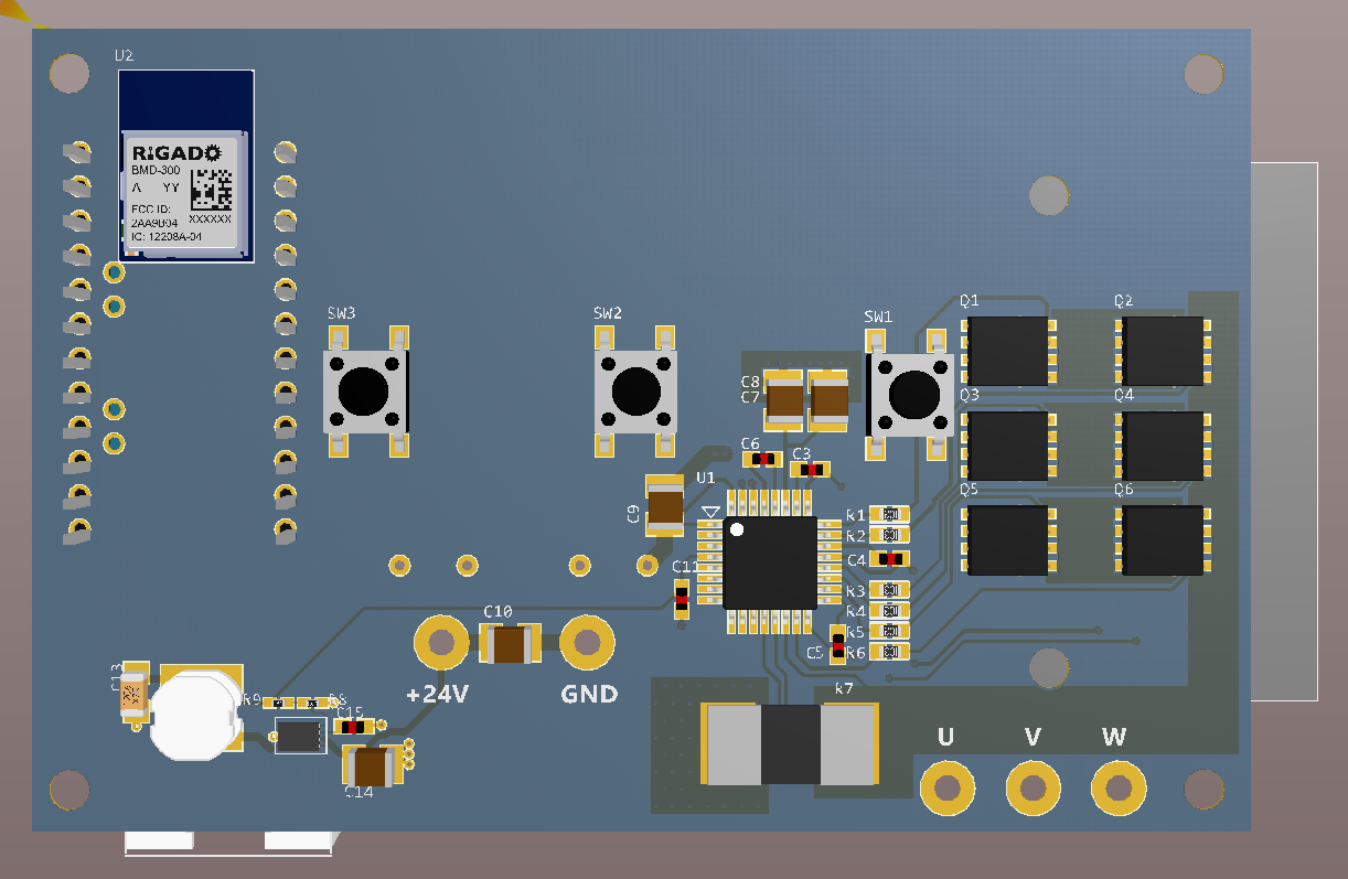
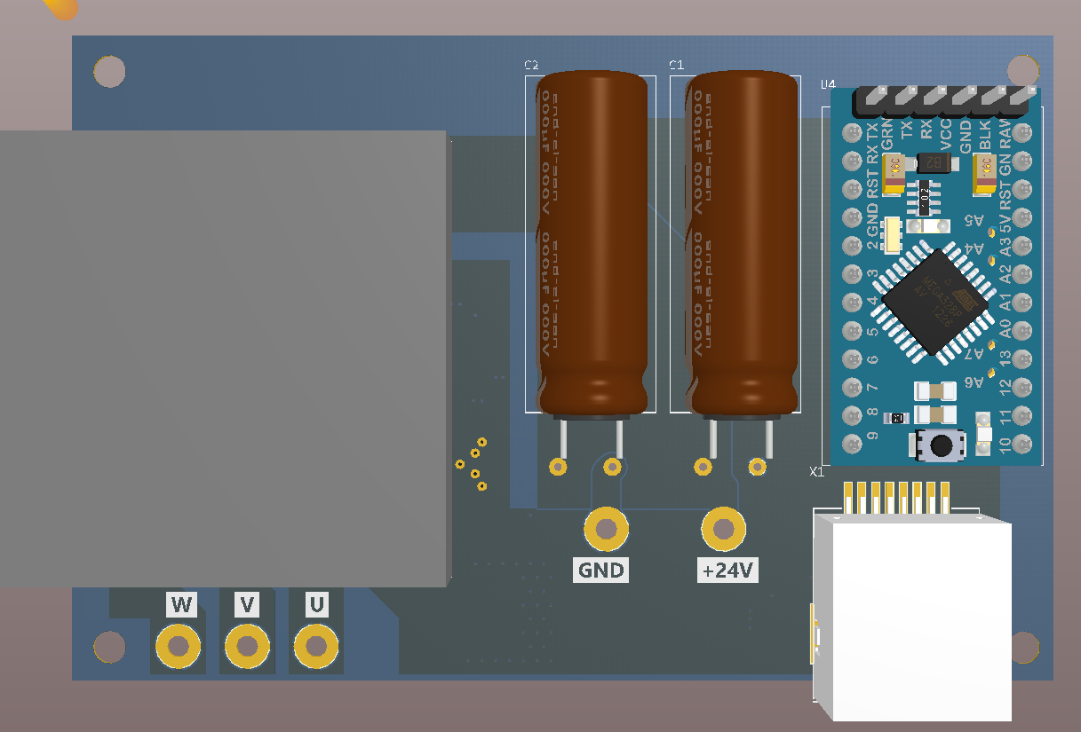
Latest models with the module + Arduino on board - the Arduino and module interfere with a few of the LEDs so it will need some scooting around.

bot-7-30.png

top-7-30.png


The buck converter is based on a MAX15062 for the logic rails. The upper end Vin is overkill but its a part I'm trying to standardize on for 5-48V VIN ranges.

can't see these images...
 
How soon to proto?

1-2 days till I can get a board ordered up. I'm missing the analog inputs and some routing of the logic lines, and some cleanup. Boards usually show up a week later, then a week for me to get around to assembling it from my queue and some vetting which can happen in parallel.
 
Yes, the white header at the bottom right will be for the APEX RJ45 connector. Two analog lines will feed into the Arduino.

I'm going to make one tweak to the design - the dual Bluetooth + Arduino module support is making everything kinda zany (keeping the antenna in a good spot, routing on two layers, LEDs, etc), so I'm making two boards: one Arduino only and one BLE only. Easy enough to do at this stage.

The arduino doesn't have enough IO for all the LEDs unless you want to employ a shift register or muxing, I'll just attach enough of them for good measure :)
 
Any word on the ebay boards with the CP-40?

--Colin

it did not work.
I hooked up the dct pump to make sure the board still works and the pump worked fine.

the cp-40 controller seem to be able to spin the dct pump just fine out of water.

so it seems there is some difference in pump startup and timing for the cp and dct pumps.

I just tested the white ebay board and it is able to spin the cp-40. the pwm has to be around 70% or higher, otherwise it does not spin. also the max power was 50watts and the fets got somewhat hot, so I would not recommend using this board on cp40, cp-25 is probably fine.
 
Last edited:
Yes, the white header at the bottom right will be for the APEX RJ45 connector. Two analog lines will feed into the Arduino.

I'm going to make one tweak to the design - the dual Bluetooth + Arduino module support is making everything kinda zany (keeping the antenna in a good spot, routing on two layers, LEDs, etc), so I'm making two boards: one Arduino only and one BLE only. Easy enough to do at this stage.

The arduino doesn't have enough IO for all the LEDs unless you want to employ a shift register or muxing, I'll just attach enough of them for good measure :)

This will be really sweet especially if its plug and play. I will defiantly but interested in one of these when they are ready.
 
Ok Arduino users (and APEX owners). I've checked this a few times, but I'm notorious for swapping key pins at times. Please check that my pin assignment for the Arduino makes sense. (I'm now used to MCUs with fully re-mappable I/O since this is 2016 after all :))

http://theatr.us/images/blueacro/dcpump/arduino-sch.png

Key lines:

A0/A1 are the analog 0-5V (divided) signal from the APEX. The pin numbers on the connector are using the RJ45 standard numbering.

PWM: This is the duty cycle control signal to the motor driver. It needs to be faster than 2kHz (else the controller sees it as a motor brake command). It should be on timer2 if I'm reading datasheets correctly.

TACH: This is a square wave signal back from the controller which gives the motor speed indicator. Ideally you'll want to capture the timing from this in order to do closed loop speed control (or at least run indication)

DIAG, RESET: Basic GPIO lines. REET resets or sleeps the controller (there is a pulldown on the controller side), DIAG is if any fault flags show up.

MOSI/MISO/SCK/CS: Standard SPI bus.
 
Back
Top