karimwassef
Active member
Which DCT are you running? I keep thinking of my 15000
I have two pumps in my sump. Each outlet on one end of the tank. The intent is to alternate a sinusoidal flow using the Apex:
<a href="http://s1062.photobucket.com/user/karimwassef/media/55_zpsr2nbcwwh.png.html" target="_blank"><img src="http://i1062.photobucket.com/albums/t496/karimwassef/55_zpsr2nbcwwh.png" border="0" alt=" photo 55_zpsr2nbcwwh.png"/></a>
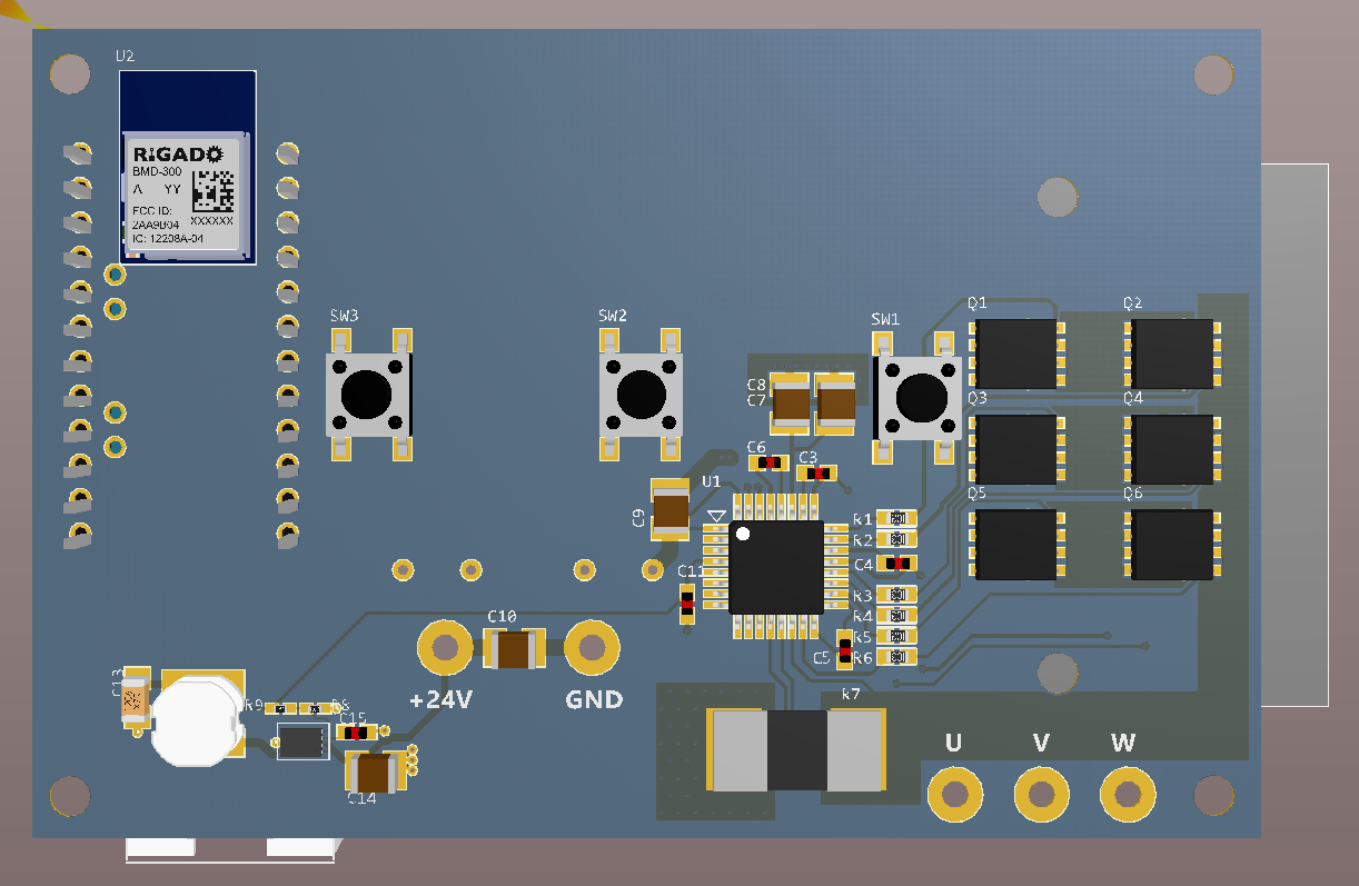
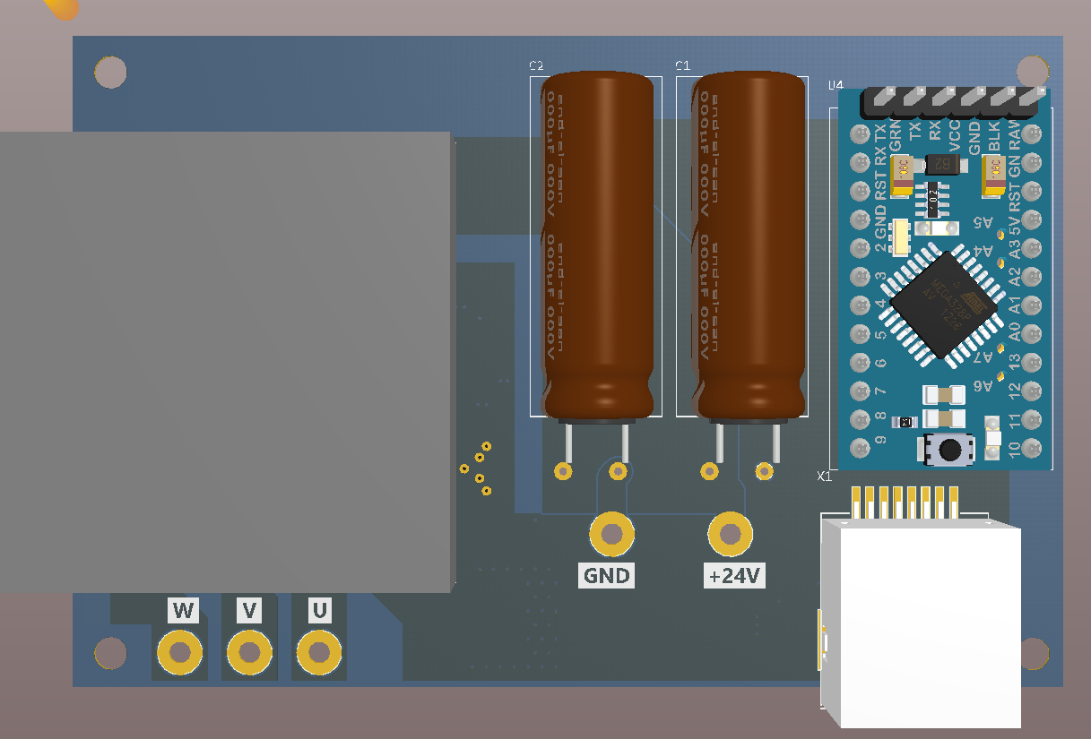
Latest models with the module + Arduino on board - the Arduino and module interfere with a few of the LEDs so it will need some scooting around.
The buck converter is based on a MAX15062 for the logic rails. The upper end Vin is overkill but its a part I'm trying to standardize on for 5-48V VIN ranges.
How soon to proto?
")
I'll try later. I'll also try the white and green ebay boards.
Any word on the ebay boards with the CP-40?
--Colin
Yes, the white header at the bottom right will be for the APEX RJ45 connector. Two analog lines will feed into the Arduino.
I'm going to make one tweak to the design - the dual Bluetooth + Arduino module support is making everything kinda zany (keeping the antenna in a good spot, routing on two layers, LEDs, etc), so I'm making two boards: one Arduino only and one BLE only. Easy enough to do at this stage.
The arduino doesn't have enough IO for all the LEDs unless you want to employ a shift register or muxing, I'll just attach enough of them for good measure
)