so I opened up the cp-40 controller, and the bemf circuit is a simplified version of the ones on the dct pump controller (1 less resistor and capacitor). So the mod on the green ebay board makes the bemf circuit identical to the jebao controller. So I think that's as far as any mod can go on the green ebay board, since the rest of the functions are in the motor controller chip.
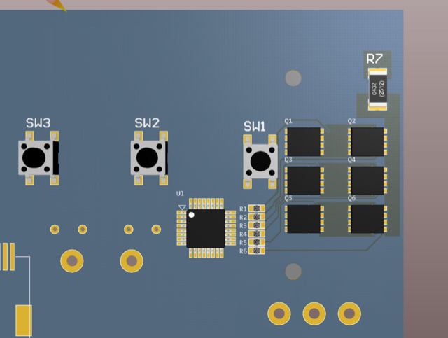
Another difference is the cp-40 controller uses a shift register to drive the leds. It has a lot more leds than the dc pump controller. The controller chip is the same as the dc pump controller, I would not be surprised if it is some version of AVR mcu. The cp-40 also use the same mosfet as the 50watt pump controller, except it does not come with a heatsink. I don't think 50watt needs a heatsink, the mosfets are still cool to the touch while running at max speed.
I will probably skip the LM339 and connect the bemf circuit directly to the Arduino. I can use the built in analog comparator interrupt to trigger commutation change. It only requires one additional pin use (4 instead of 3) as the reference is now used as comparator positive input.
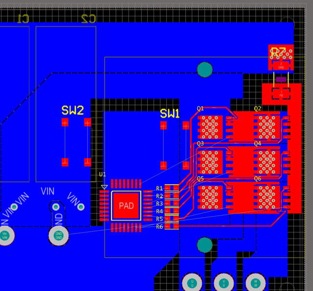
I'll trace the motor driver circuit on cp-40 controller tonight and will probably use the same circuit. I think the reason you can only use 24v is the mosfet max Vgs is 20v so the pre driver must not use >20v. I think it uses 18v.
Apparently, the reason the ebay sellers dropped the price of crossflow is jebao is coming out with a new version. No further info on what changed.
") I usually host the images out of my blog system but sometimes post from the phone.
I usually host the images out of my blog system but sometimes post from the phone.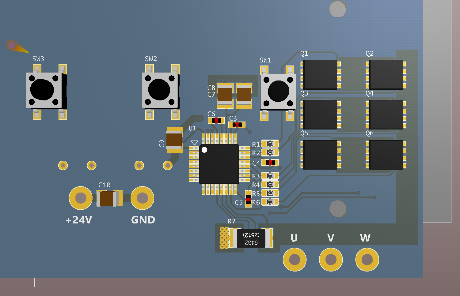
")