Use PWM to control your Jebao DCT pump using brushless motor controller from ebay

Following this thread, I have a jebao 6000 and want to tie to my apex so I can slow my main pump down at night. I was going to get a Waveline and keep the Jebao as a spare but I have read Wavelines are not holding up and are terrible to deal with for service. This will probably be overkill for the 6000, what power supply would you recommend, I hear that is the weak point of the Waveline.
Bill
 
I have TWO Jebao DC12000(Returns) and a DC6000(Skimmer) in the sump and a pair or PP15s ( the new RW15's ) in the tank.

It would be nice if I could set feed mode on 1 unit and all of them automatically follow "suit"...
 
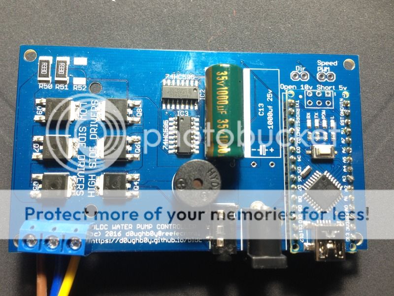
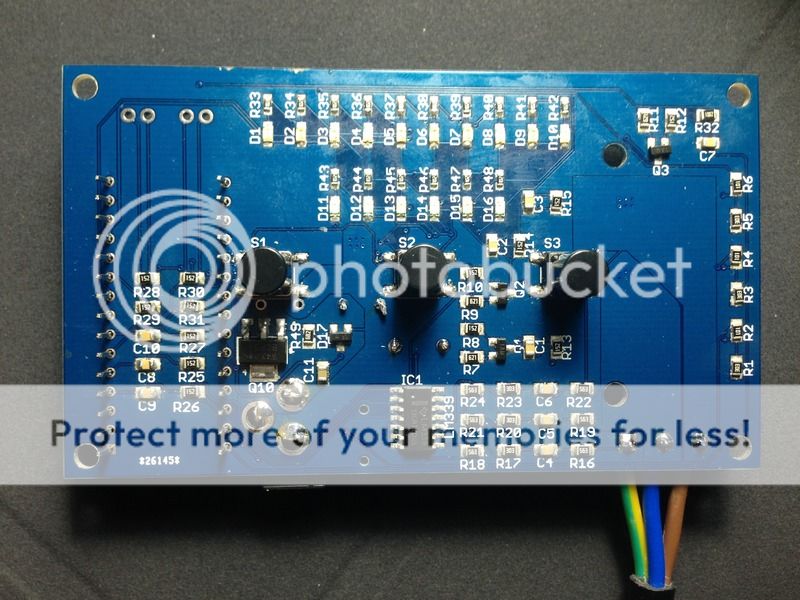
Got the pcbs and just finished assembling one. Still have some loose connections to fix, but this is what it currently looks like. I'll be resuming work on the software.

IMG_2100.jpg~original


IMG_2104.jpg~original
 
Last edited:
Very nice. Haven't had any time on mine, but want to get it running so we can do some comparisons.


Sent from my iPhone using Tapatalk
 
Nicely done, just curious how you are doing you smt solder work. Theatrus gave a nice write up on how he does his and was very informative. My hands are beginning to shake and pick and place and hand soldering is becoming difficult. This is very interesting to me as I used to sell reliance inverter drives and soft starts when they first came to market. I am amazed at the technology even the esc and motors used in the quadricopters. I hope you will show some kind of graphic display of the ramping of the wave forms and for different conditions. It might be nice to add an automative reversing of the motor to purge the occasional snail.
 
100% hand solder using soldering iron and hot air. it is not exactly easy. Those LED resistors are 0603 size, the rest of passive components are 0805.

I found a problem with the circuit. The pre-regulator output is 15-16v, and the AMS1117 regulator on the Arduino nano has max input of 15v so there is no 5v output (not sure if it got damaged or just shut down). I have to change the zener on the pre-regulator so the output is <15v. Hopefully it should not affect the LM339 circuit if its power goes down by 1v. The stock controller uses 78L05, which has max input of 30v.
 
I just ordered 12 and 15v zener diodes. Should be able to test the new circuit next weekend. Using 16v zener, I measured 15.1v output, so I think the 12 or 15v zener should work fine. I think the rest of the circuit should be fine, the BEMF voltage divider drops the voltage to around 9v max.

regarding soldering, the hardest part was soldering the mosfets and the voltage regulator transistor, as the terminals are attached to large pads for heat sinking.

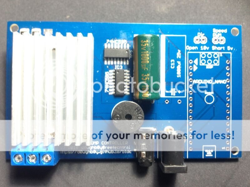
heatsink from jebao controller attached to the new board.
or you can use the standard 40mmx40mm cpu heatsink glued to the mosfet using heatsink glue

IMG_2105.jpg~original
 
Last edited:
100% hand solder using soldering iron and hot air. it is not exactly easy. Those LED resistors are 0603 size, the rest of passive components are 0805.

I found a problem with the circuit. The pre-regulator output is 15-16v, and the AMS1117 regulator on the Arduino nano has max input of 15v so there is no 5v output (not sure if it got damaged or just shut down). I have to change the zener on the pre-regulator so the output is <15v. Hopefully it should not affect the LM339 circuit if its power goes down by 1v. The stock controller uses 78L05, which has max input of 30v.

God bless, I tried doing something similar a few years back by hand. Never again :headwalls: Looks awesome. Cant wait for the results.
 
Highly suggest trying a stencil from OSHStencil, they now also sell small quantities of paste, and grabbing a skillet or toaster oven. It makes the large thermal pad components trivial.
 
I'll probably get stencils if I do another pcb order.
is 0.75 stencil border ok? the default is 1.25" border.
3 or 5 mil?

I'm getting better at applying solder paste manually to the pads. But it is quite tedious to do it pad by pad.

I'll probably try with a skillet.
 
Shorter border is just fine - this is mainly space to tape it down. I just use old scrap boards to make a holder, lots of blue tape.

3 mil is great. 5 might be more durable, but you'll also be adding more solder to each pad which is no good for fine pitch components. You'll also want to reduce the size or pattern any large fills on QFNs or the like, as filling the whole space will cause solder to bridge from the center to the pins.


Sent from my iPhone using Tapatalk
 
ok, got the parts and replaced the 16v zener with 12v zener. Now the pre-regulator output is 11.1v. I confirmed the Arduino nano regulator is toast. They sure mean it when they say absolute maximum input rating is 15v if 15.1v destroyed it. I am using my last Arduino nano. I have to order a few more for spare.

I have tested the shift register and LED circuit and it works fine. The green led seems brighter than the blue one. I use 1k resistor for the leds.

I'll start working on the software next. first things first, I need to get the motor to spin at full speed first.
 
all the pins of the Arduino are used. the rx tx in theory can still be connected to an esp8266, but not sure if the Arduino will have enough space to hold the program. I want to keep the program for this controller small and stable, and do any communications from another Arduino (or teensy 3) that has the esp8266. and the controlling Arduino controls the pump controller boards via pwm and direction pins.

I'm taking this one step at a time.

my shift register/led program stopped working when I plugged in the 24v. I need to find out if the shift register chips got damaged.
 
I have a Deepwater Aquatics BLDC8 DC return pump and plan to get a second one a smaller one. The manufacturer says they "have a 0-10V input for variable speed control."
Would one of these work with it? OR can I just use my AquaController Surf wired appropriately?
 
If it has the input, the pump controller already should support speed control from an analog voltage.
 
no update since last time.
I thought the board was ready for more software development, then it stopped working and not sure which component is the problem. Then I had other things to attend to. I'll be assembling another board (maybe try using a skillet) sometime later this week.
 
I assembled a second board. used skillet to solder the 6 power mosfet. I think the result is cleaner. Anyway, I used 15v zener in the pre-regulator circuit, and output is 14.7v and use that to feed the Arduino nano. I ran a test program just to light the 16 leds and in less than 30 minutes, the board is dead. It looks like the 5v regulator on board the Arduino got damaged again. I don't think the entire circuit is using anywhere close to 100ma even with all 16 leds on, so I think the AMS1117 regulator is just not able to handle input voltage close to the 15v limit.

Anyway, I just repaired the first board and kept the 12v zener and I am running the same led test again. if this one survives after 24 hours, then I will proceed with the software work.
 
Back
Top