Use PWM to control your Jebao DCT pump using brushless motor controller from ebay

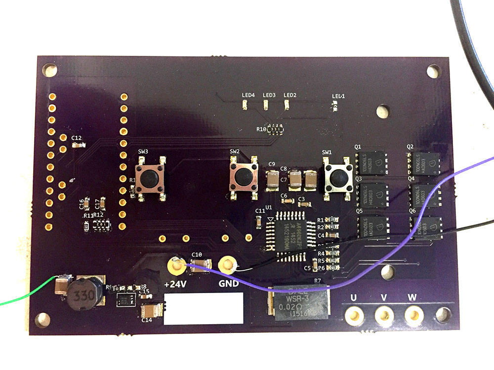
The led shift register test worked fine for a day, so I think the power supply circuit is now good. I may change the circuit on next revision to use its own 7805 regulator and just feed to Arduino 5v pin. On the second board, I soldered the Arduino to the board and it is impossible to desolder without damaging anything, so my second board is now completely unusable/unrepairable.

I started testing the motor driver code on the other board, and a pair of mosfets got damaged, I think due to cold solder/bad connection. I am going to repair that next and hopefully no more circuit issues so I can focus more on software work.
 
fixed the first board. got it to work like the breadboard circuit pump spins in open loop code. I can now resume work on code to get it to spin in closed loop.
 
loaded.jpg

Are you going to be selling these boards as well ??
 
still working on the Arduino code.
when pump is dry, the code works, even the soft start routine works.
when the pump is in water, it does not work. I figure maybe there is not enough current to turn the impeller so I set my starting current higher, it still does not spin (it starts momentarily then stops). I think it may be timing related. I can tell the higher current is working because when the pump stops, and I try to manually turn the impeller, I need to use a stronger force to turn it. So I think its just a matter of refining the code to adjust for load.
on no load run, I logged the time and interrupt sequence and they are all in perfect sequence. I think the circuit itself is now good/final.

I see maxspect released a dual pump controller. The plan for this diy design is to add another circuit (or use apex) to orchestrate multiple driver boards, so will not be limited to controlling 2 pumps.
 
interesting they used dip switch to program parameters for different pumps.
It is essentially a motor driver with speed and direction control for apex (0-10v only), also has limit of 4amp, so can't be used on dcs-15000 pump.
This diy is going to have the same function as stock controller plus the speed and direction control and will work up to 6amp (150w pump).
 
a cold solder on an Arduino pin was causing the pump to not spin. so it turns out the pump spins when in water as well. The problem I have now is it is not spinning as fast, and it looks like the bemf interrupts seems to be occurring late, hence the pump is not spinning fast enough. I have to capture and study the signals to find out what is causing this.

The only difference from the stock controller circuit is I am using 12v for pre-regulator instead of 16v. I don't think it should affect the circuit operation, but that is the only thing I can think of that is different.
 
I think the bemf delay may be due to using capacitor value that is too high. since smd capacitor has no markings, I just used 100nf. I will try different values 100pf, 1nf and 10nf and see if that will give a better bemf signal timing.
 
interesting they used dip switch to program parameters for different pumps.
It is essentially a motor driver with speed and direction control for apex (0-10v only), also has limit of 4amp, so can't be used on dcs-15000 pump.
This diy is going to have the same function as stock controller plus the speed and direction control and will work up to 6amp (150w pump).

I have been following your thread with interest, although limited knowledge in comparison to you. How do you know the 4amp limit? The manual they list does state the dct-15000 can be controlled, but I don't know the specs on dct/dcs 15000, I thought they were the same with different controllers.

How much do you think your end product will cost, and do you plan to sell to the public or at least RC memebers? I'm sure theres an interest.
 
I have been following your thread with interest, although limited knowledge in comparison to you. How do you know the 4amp limit?

We do know that the Operating Voltage of these pumps is 24VDC so with a bit of math...

W = A x V

105W @ 24V = 4.35A
155W @ 24V = 6.46A


The manual they list does state the dct-15000 can be controlled, but I don't know the specs on dct/dcs 15000, I thought they were the same with different controllers.

The Older DC models have the controller built into the motor and the "control box" is nothing more than a PWM Generator. n the newer pumps, DCT/DCS the controller is quite a bit larger and now it also houses the rest of the electronics. The wattage readings differ from site to site and seen 105 and 155 rating for the 15000 unit.
 
ok, I could have sworn in the original link, which does not work anymore, did not list dct15000, but do see it now in the updated manual.

I did not have much time to work on this lately. I got the different capacitors to test, and tried the 1nf, and it still did not work, though I think it might be a loose connection issue. I have not had the chance to work on it further.

there are many ways to diy this, including using the TI chip. who knows, I may end up trying that if I don't get anywhere using the Arduino.

I need to make this work first before I figure what to do with it.

So far, I think due to the difficulty and challenges I had to deal with, it may not be a feasible diy for anyone to do. There are too many things that can go wrong.
 
SNIP

So far, I think due to the difficulty and challenges I had to deal with, it may not be a feasible diy for anyone to do. There are too many things that can go wrong.

I had everything worked out on paper but never got any further as work picked up and have little to no time... but then again everything looks great on paper lol
 
ok, I could have sworn in the original link, which does not work anymore, did not list dct15000, but do see it now in the updated manual.

I did not have much time to work on this lately. I got the different capacitors to test, and tried the 1nf, and it still did not work, though I think it might be a loose connection issue. I have not had the chance to work on it further.

there are many ways to diy this, including using the TI chip. who knows, I may end up trying that if I don't get anywhere using the Arduino.

I need to make this work first before I figure what to do with it.

So far, I think due to the difficulty and challenges I had to deal with, it may not be a feasible diy for anyone to do. There are too many things that can go wrong.


Since I've had zero time on my design, I can send you the board + Arduino for the Allegro based driver for some firmware development time. Let me know if you're interested.
 
Since I've had zero time on my design, I can send you the board + Arduino for the Allegro based driver for some firmware development time. Let me know if you're interested.

sure. I'll probably have time to work on that in a few weeks.
 
Need some help here guys.
After connecting the green board to my Jebao DCT-4000 pump, I realized that the water flow coming out from the pump is very slow. I mean much slower than original Jebao controller. And the pump is also running at louder noise than the original controller.

It is clear that the pump motor is not running under the optimal state. I am connecting VR directly to Arduino 5V pin.

What could be my issues here?

Thanks.
 
Back
Top