Use PWM to control your Jebao DCT pump using brushless motor controller from ebay

its flu season, I already got two rounds since december.
hope to resume as soon as I can.
I figure since fish-street has put out a version that accepts apex 0-10v input, those who cannot wait have that option.
 
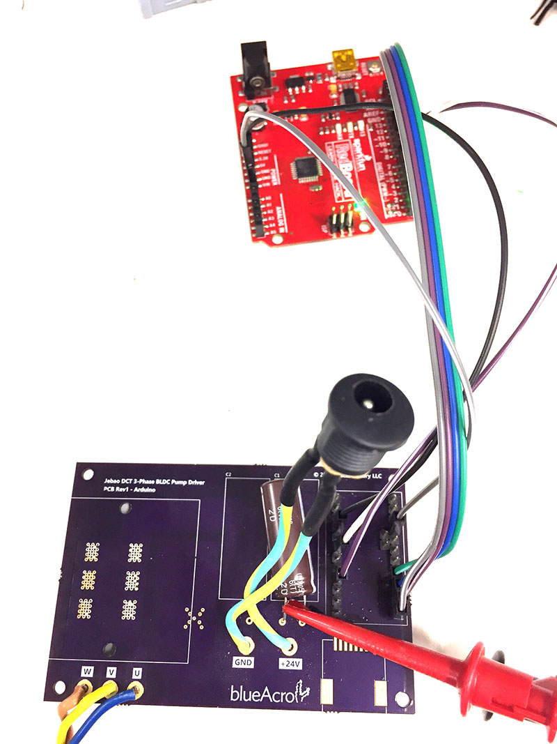
ok. here's what I'm wiring up right now. I like to cover all the details just to be 100% sure it all ties out.

<a href="http://s1062.photobucket.com/user/karimwassef/media/0_zpsdcgx42zb.png.html" target="_blank"><img src="http://i1062.photobucket.com/albums/t496/karimwassef/0_zpsdcgx42zb.png" border="0" alt=" photo 0_zpsdcgx42zb.png"/></a>

any issues?

Hi, need some help please. I have a DCS12000 and my controller is damaged.
if I use the diagram to DIY a controller for full power to the pump will it work on the DCS12 000 without the Ethernet connection.

any idea please?
 
We never got a DIY controller that could deliver the same full power as the native controller.

This maxed out will get you to ~50%. Anyone else have more success?
 
Updates:

I have my A4960 based controller running at full pump (30W for the pump I'm testing) power levels and with speed control - more details soon!

(This is in water, but not constricted, ymmv and more testing to be done).
 
Temporary wiring:

wired.jpg


Running at 100%

bucket.jpg


ps.jpg
 
Notes:

- Commutation doesn't work in air - it needs motor drag to reliably run. A bit odd, may be solvable.
- There are a few cases where startup commutation doesn't work. I've only hammered at the rough settings on the IC so I haven't hit the right combo, have spent zero time analyzing the timing.
- The 1kHz PWM signal from the Arduino is useless - a drive signal at about 10kHz-15kHz seems to be the sweet spot - I'm feeding this with an external generator right now. Duty cycles down to about 40% work well, at which point motor power is at the 5W point.
- The driver PCB stays cold.

More details soon.
 
How much power can the board handle?
Why 15 kHz? Is it the pulse timing for the commutation that's driving the resolution?
 
Based on current evidence, the FET drivers could handle the large DCT-15000 pump, however the currently installed current shunt limits the current and that pump caps out before it gets anywhere close to 100W average.

The DCT-4000 and 6000 run at their rated power.

Of course you can already buy a controller for Apex-to-DCT (would love a teardown), but this is at least pretty universal for sensorless motors.

The PWM signal is effectively coupled directly to the FET drive, so if your frequency is too low you'll have your drive off for most of a phase, hence it will rapidly stall the motor. One quirk is the controller still sees BEMF and thinks its running when the rotor is stalled - there is some nasty EMI flying around here likely contributing to this.
 
I got one of those. Want me to take it apart for pictures?

Actually, if you really want, I'll send it to you for diagnostics.

As long as I get a "materials cost" build of your version when it works... LOL :)

I'm serious though :D
 
I got one of those. Want me to take it apart for pictures?

Actually, if you really want, I'll send it to you for diagnostics.

As long as I get a "materials cost" build of your version when it works... LOL :)

I'm serious though :D

Pictures are fine - either it will be a known controller, or an unbadged or unknown/MCU driven approach.
 
so for the fish street controller, how do you configure it to work with the different dct pumps and the cross flow? dip switch?

I figure this is to switch the current sense resistor value. I don't think the start and run sequence would be any different
 
so for the fish street controller, how do you configure it to work with the different dct pumps and the cross flow? dip switch?

I figure this is to switch the current sense resistor value. I don't think the start and run sequence would be any different

The manual shows DIP switches for the various pumps. And yeah, I imagine its just the current limit.
 
Back
Top