Use PWM to control your Jebao DCT pump using brushless motor controller from ebay

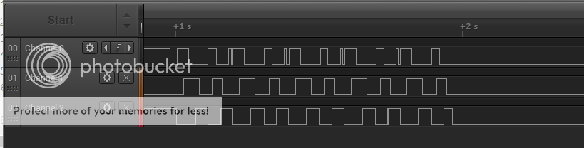
Yay! Making progress. Pumps spinning is a good sign of progress :)

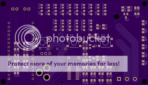
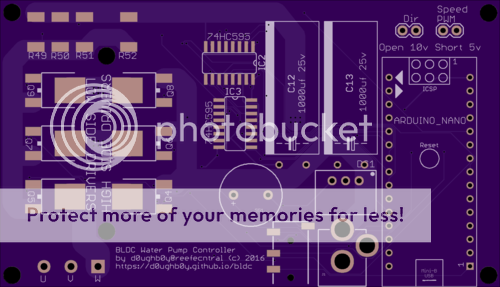
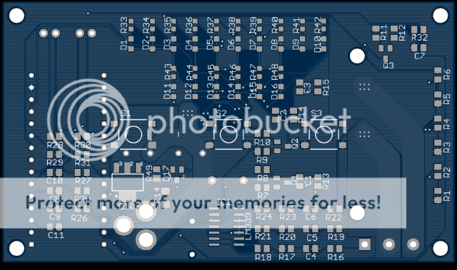
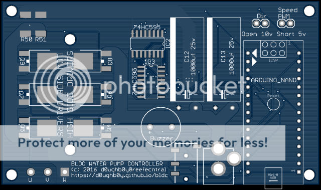
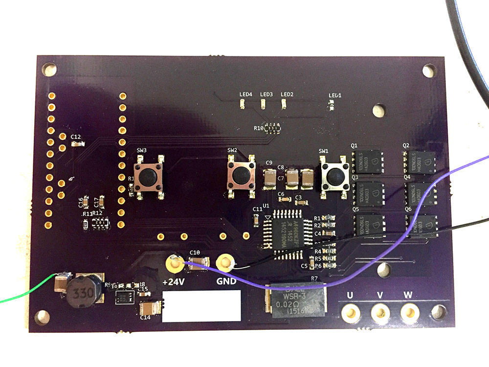
I only got so far as loading parts onto my controller board, and then being unable to find the matching Arduino board. Too many builds in progress between the LEDs, controllers, and mechanical parts. Upside: at least the 5V supply works.

loaded.jpg
 
bemf signal coming from lm339 during open loop startup.
somehow, the pin interrupt on Arduino is not working properly. Once I get it to properly interrupt, I can test the code to switch to closed loop commutation.

startbemf.png~original
 
Last edited:
ok,I had a misconnection and damaged the LM339, so need to get another one tomorrow.

The bemf signal has a lot of noise/ringing. if you look at the bemf signal, you will notice the edges are thick. That's why the interrupt was going crazy. I'm still figuring out a way to debounce the signal either in software or hardware.

The bemf commutation requires one timer interrupt. The problem is I already used 2 and one is used by system milllis. So I have to figure a way to switch the two timers I am currently using for pwm to switch function from pwm generation to timer interrupt.
 
I've never had the best luck with pin based interrupts. I always end up making my own using one of the digital pins. That allows me to debounce the input in software. I honestly haven't read all of this, so I'm not 100% sure what you're using the bemf for.
 
working on pcb routing all weekend. I'll check it a few more times for error and will probably order the pcb this week.

The board uses a DC jack for power input. pwm and direction signals use an audio headphone jack. The signal voltage level is jumper selectable. Jumper open is for 10v signal, shorted is for 5v signal.

The board should be able to handle 150watt pumps, possibly 180watt pumps. You can either use the existing heatsink from the stock controller, or get one of those 40mmx40mmx10mm heatsink from ebay.

The size of pcb will fit a 100mmx60mmx25mm plastic enclosure available on ebay for about $2. There will be a lot of drilling/dremelling involved though.

This is the top
bldc_top.png~original


This is the bottom
bldc_bot.png~original
 
Last edited:
I revised the circuit to use the same zener voltage regulator as the stock controller and will submit the pcb order this week. I just need to get the proper bemf signal timing and the rest of the code should be fairly straightforward. I can work faster on the software once I get the pcb.
 
surprised that no one went looking for something a bit more integrated and better suite ( overkill ) for the task...

Such as GIPS30C60-H

I think this may easily reduce the component count not to mention gives one a massive overhead allowing one to keep/use the same controller for a long time.
Not to mention sample availability...


An IGBT gate driver is... not suitable.

The A4960 is a perfect integrated controller, I've just had zero time to test my board :(
 
I was going over the stock controller boards to make sure I did not miss anything and noticed the dct pump controller has a temperature sensor (the cross flow controller does not). I was thinking of adding the temp sensor but I have used all the Arduino pins and will have to move one of the pushbutton to use the serial RX pin.

But come to think of it, if max controller current is about 6+ amps for DCT15000, the current sensor should be enough protection to shutdown the pump, since the temperature is a function of the current, I think it is ok to omit the temp sensor as long as a heat sink is used.

based on mosfet datasheet, running it at 4 amps continuous (about 100watts) without heatsink will get a temperature of about 100F. considering each fet pair turns on 1/3 of the time, so the temp for each fet will be less.
 
you can use a controller like Neptune or reefkeeper that has pwm or variable analog out to control multiple pump controllers. if you do not have a fancy controller, you can use another Arduino to generate the pwm signals to control multiple pumps.
 
you can use a controller like Neptune or reefkeeper that has pwm or variable analog out to control multiple pump controllers. if you do not have a fancy controller, you can use another Arduino to generate the pwm signals to control multiple pumps.

Works for me :)

I'm guessing PWM would be fed VIA the 3.5mm jack ?
 
waiting for pcbs to arrive, probably first week of November, then resume working on the firmware. It was getting quite difficult to work with the breadboard circuit.
 
I just thought of this...
An ESP8266 / NRF24 module for wifi control or integration with other Jebao wifi units such as the new wifi powerheads would be great.
At least this way some of the code can be copied from the wifi units and partly implemented ( Feed function ).

Not to mention this opens up a whole new level of customizing since these modules are dirt cheap and easily can be programmed to integrate with one another !!
 
Back
Top