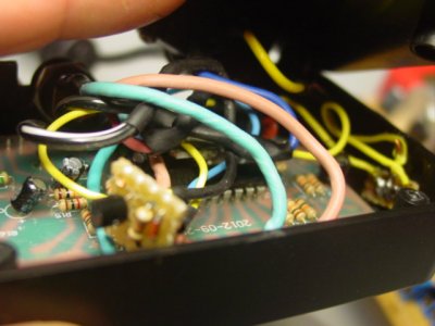
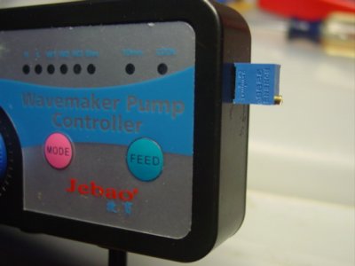
Awhile back someone explained how to install a pot on the VA line. It does work, but you lose all top end. The addition of three more parts fixes that. I put this in the controller box after trimming the board way down. Now, I can adjust all modes for intensity from wide open to crawl as well as frequency.
But three wires broke from all the jiggling and it was a pain to fix. At one point, I thought I ruined the controller. All is well, it works like a champ, but there is risk.
Here are the parts I used.
http://stores.ebay.com/Tayda2009/_i.html?_nkw=1n4148&submit=Search&_sid=872591586
http://stores.ebay.com/Tayda2009/_i.html?_nkw=2n3906&submit=Search&_sid=872591586
http://stores.ebay.com/Tayda2009/_i.html?_nkw=25k+trimmer&submit=Search&_sid=872591586
http://www.ebay.com/itm/50-x-Resist...617?pt=LH_DefaultDomain_0&hash=item3a673ad749
I did not figure this out. A friend whom I rarely see whipped it out in a heartbeat. In the rough schematic, the base of the transistor is connected to the controller (5V line) and the wiper of the trimmer is connected to pump (5V line)
I can't imagine why Jeboa did not do this from the getgo. Lose the low setting and do this.:hmm4:
Can you post a pic?
Sent from my SGH-i777 using Tapatalk 2