Durso standpipe?

Would could you run flexible PVC pipe from the pump up to near the return? I think I would need to switch back to hard PVC to put a check valve to prevent back siphoning?

Can you use an union to switch from flex to hard PVC?

Also, where can you buy the pipes and joints from? does it have to be reef safe or can you just buy the standard pipes from Home Depot or Lowes?

Uncle, where did you get all the BeanOverflow flow rates from (pipe size to flow rate)? Can you post a link? Thanks
 
Would could you run flexible PVC pipe from the pump up to near the return? I think I would need to switch back to hard PVC to put a check valve to prevent back siphoning?

Yes you can and no on the checkvalve. Checkvalves in saltwater tend to be unreliable. No need for them at all. Either have the return just barely under the water, or drill a small hole in the pipe near the surface... that will solve all siphoning issues. Its usually easier to just have the return line (I use link-loc) just beneath the water surface, if you sump is big enough you can have it deeper, just depends how much extra water your sump can hold.

Can you use an union to switch from flex to hard PVC?
Yes, but can also just use a coupling.


Also, where can you buy the pipes and joints from? does it have to be reef safe or can you just buy the standard pipes from Home Depot or Lowes?
Regular ole PVC pipe. NO COPPER
 

Don't apologize, you are here to learn aren't you?

Thanks for the link. What makes the waveline so superior to the Tunze, just curious, I read some articles but it doesn't mention much about the new technology that you mentioned, the soft start feature and variable speed are nice features!

Nothing new about a variable speed DC motor. Is easy to do, a packaged variable speed AC motor (with built in VFD) would be interesting to run. It is a relatively new pump. And looking at the specs, you can see it knocks the snot out of the old standbys. ;) You want to go much higher than this tank, you run out of options rather quickly, other than the larger reeflos such as, the Barracuda, Hammerhead, and beyond.

I will still probably use a small separate pump to run water through the reactors and into the Refugium, I just think that will be easier, and it only needs to be a small pump to filter through the reactors and sump.

I am trying to make it simple for you, and you want to keep making it more complicated. :celeb2:
This is really simple.

sump3-7.jpg


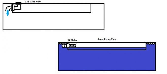
What you have to remember though, is I recommend against splitting the return like this. This was done for someone that just would not let it go. ;)

To run your reactors, you tap the branch off the return line. On the other hand, reactors are a "down the road" addition to the system. They are a waste of time on a new system. For one, you have no idea what you are going to need. Sure, they are recommended all the time; that does not make them necessary, or in some cases--even desirable. It is important to learn how to manage a system, without such crutches. That way, when things go rotten on you, you know how to deal with it. You won't panic, start a thread, and have everyone tell you how to do it, every way but the right way. This happens a great deal with calcium reactors; GFO can casue you problems as well.

My only concern with that is that some of the water will go back to the DT without going through the reactors, is that something I should be concerned about?

Putting it bluntly: Who cares? ;) Not me--nor should anyone else be concerned about it. No one should have a concern about slowing the flow rate through the sump down, so all the water will go through the skimmer, either. For some unknown reason, that is a great debate starter. That won't happen, no matter what you do, anyway.

What occurs is cumulative, not one pass. So you need not be concerned about the percentage of water flow through here or there--the important number is what is flowing to and from the DT.

I've looked on the BRS site, can't find anything mentioning optimal flow, think 600GPH split between 2 reactors should be adequate, right?

Maybe you should start looking somewhere other than the BRS site then. I can't help you here, it depends on the reactor itself, and the type of media. You are likely to get as many different answers as there are people running them.
 
Would could you run flexible PVC pipe from the pump up to near the return? I think I would need to switch back to hard PVC to put a check valve to prevent back siphoning?

You can run spa-flex, just be aware it is not as flexible as the name implies. It can be made flexible: by heating it up, with a heat gun. But, then--so can hard pipe.

Can you use an union to switch from flex to hard PVC?

Spa-flex uses standard sch 40 pvc fittings. I recommend minimizing the number of unions in an aquarium set up. They are potential leak points. Setting up simple plumbing schemes reduces the need for them.

Also, where can you buy the pipes and joints from? does it have to be reef safe or can you just buy the standard pipes from Home Depot or Lowes?

Of course. You will run into a problem locating sanitary tees for the drain system however. HD and Lowes do not carry them. They are made in 1.5", most commonly found, and 1.25"--a little bit harder to find.

Sanitary tees are not required, but they do reduce the turbulence in the drain lines.

Uncle, where did you get all the BeanOverflow flow rates from (pipe size to flow rate)? Can you post a link? Thanks

It is a simple application of Bernoulli's Equation. You will find a calculator on Bean's website. Just be aware, that these are ballpark max theoretical numbers for flow through a bulkhead. Real life, will be less due to friction loss in the pipe.

http://www.beananimal.com/articles/hydraulics-for-the-aquarist.aspx

You will also find some comments on the Waveline DC-5000 there also. (something neither Bean nor myself do: post reviews of equipment)

http://www.beananimal.com/other/waveline-dc5000-variable-speed-dc-pump.aspx
 
Thanks Uncle, that calculator is awesome.

So I was going to use 1" bulkheads and use 1.5" pipes but the calculator says I will have a flow rate of about 2300GPH down the full siphon pipe. (it says to use the smallest diameter water will flow through so I put 1" in that box as that is the bulkhead diameter?)

Do I need to calculate in the flow of the open channel drain?

If I use the Waveline with the height in there, about 50", that's gonna be like 1750GPH without any friction loss, so is that going to work?

2300GPH drain and 1750GPH Return? If I go down to .75 on the drain, then I'm going to only have 1300GPH flow from the drain.

Just not sure if I have overlooked something?

That's why I'm reluctant to use the return pump to feed the reactor and fuge? but like I said, maybe I have overlooked something.
 
Looked everywhere. Cant find the outlet size for the waveline, any idea what size it is, or where to find the size?

Thanks
 
Looked everywhere. Cant find the outlet size for the waveline, any idea what size it is, or where to find the size?

Thanks
 
Thanks Uncle, that calculator is awesome.

So I was going to use 1" bulkheads and use 1.5" pipes but the calculator says I will have a flow rate of about 2300GPH down the full siphon pipe. (it says to use the smallest diameter water will flow through so I put 1" in that box as that is the bulkhead diameter?)

Having the calculator, doesn't do much good if you don't know what the numbers mean, and how this all fits together. That is why I just post the numbers, rather than the link to the calculator. Kinda like buying a lens for a camera you don't have. :)

Smallest diameter determines the flow rate. The pipe size determines the friction loss, or how much will flow real world.

Do I need to calculate in the flow of the open channel drain?
No.

If I use the Waveline with the height in there, about 50", that's gonna be like 1750GPH without any friction loss, so is that going to work?
Where did that number come from? According to the flow curve for the DC-10000 on the RLSS website, this pump will flow 8000 lph @ 2 meters. That is ~2113 gph @ ~ 6 feet, for those that don't speak metric.

2300GPH drain and 1750GPH Return? If I go down to .75 on the drain, then I'm going to only have 1300GPH flow from the drain.
Why on earth would you want to reduce to .75". That would make no sense at all. :)

Just not sure if I have overlooked something?

That's why I'm reluctant to use the return pump to feed the reactor and fuge? but like I said, maybe I have overlooked something.
You are over thinking it. Either I know what I am talking about or I don't. I told you how to get there. :)

Incidentally, have not heard of reactors needing 600 gph--too many are scared to death to flow that much to their DT. Generally they are rather slow flow. I don't use the things--so maybe, things have changed. Like I said before, they are an add on later thing, that are not needed on a new system.
 
I must have read the flow curve wrong I'm sure I saw that at 5 feet it was 6000 lph, that's why I was wondering if I needed to make the drain size smaller to .75, I figured having water drain faster than you can pump it back up would be a bad idea.

I will look at the flow curve again, I probably misread it!

How much friction on the drain can I account for?

Is it a problem that the return is 200gph less than the drain? I was going to use 1" bulkhead, with 1.5" pipe on all the drains.

Question, should I consider making the full siphon drain 1", thus increasing the friction and slowing down the rate that water travels through the drain, bringing the drain rate down below the rate of the return, then tuning the return to equal it out.

All just questions, am I over thinking this? I'm imagining that the rates have to be really close to avoid issues.
 
I must have read the flow curve wrong I'm sure I saw that at 5 feet it was 6000 lph, that's why I was wondering if I needed to make the drain size smaller to .75, I figured having water drain faster than you can pump it back up would be a bad idea.

The left hand column in the flow curve is meters, not feet. @ 2 meters, ~ 6' the flow is over 8000 lph......

A little story. Whatever goes up must come down. So if you throw a ball up in the air, a ball is going to come down; a lesson in Physics (Gravity.)

If you throw a ball up in the air, it is impossible for two balls to come down. Another lesson in Physics: If you don't send it up, it cannot come down.

So if you send x amount of water up to the tank, it is impossible for z (x + y) amount of water to come down, because the "y" value was not sent up to the tank.

The moral of the story is: if you send x amount of water up to the tank, the drain is only going to flow x amount of water, even though it may be able to handle z amount of water.

I will look at the flow curve again, I probably misread it!

How much friction on the drain can I account for?

I would be guessing, but you would lose maybe ~ 100 gph, give or take, with 1.5" pipe. Could be more.

Is it a problem that the return is 200gph less than the drain? I was going to use 1" bulkhead, with 1.5" pipe on all the drains.

No. What is a problem is if the drain is 200 gph less than the return--that is possible, in the grand scheme of things.

Question, should I consider making the full siphon drain 1", thus increasing the friction and slowing down the rate that water travels through the drain, bringing the drain rate down below the rate of the return, then tuning the return to equal it out.

No. Just FYI, when I go above 1500 gph towards 2000 gph, I use 1.5" bulkheads.

All just questions, am I over thinking this? I'm imagining that the rates have to be really close to avoid issues.

You are over thinking it. What goes up, is all that will come down.
 
Genius!!!! Thanks so much uncle, you are a pro!

That makes it so much less complicated! I was all worried that I had to match the flows to avoid flooding the sump.

One less way of flooding to worry about :celeb1

Last 3 questions, Schedule 40 pipe and fittings throughout be good?

Can i get away with using just one ball valve (on the siphon drain), perhaps a gate valve instead?

I'd like to drill a return hole, to avoid going over the back of the tank with the return. If I do this, how do I avoid back siphoning? I saw your posts saying check valves and the little air holes don't work, so interested to see if there's another method?

If I went over the back, I could drill the little holes near the surface to break the siphon. If I drill the return, I'm going to be at least an inch from the surface? That could be over 10 gallons prior to the siphon break.
 
I tried posting this earlier, so hoping this is not a double post.

Thanks so much Uncle, that is a great explanation, you are certainly a PRO. That makes it all so much simpler, I was all worried that I had to get the flow rates equal to avoid flooding the sump.

Whooo! that's one less way of flooding the house to worry about!

Last 3 questions, I promise.

Plan on using schedule 40 pipe and fittings throughout (except bulkheads)?

Can I get away with using only one ball valve, just on the siphon pipe? Gate valve preferred?

How do I prevent back siphoning on the return line? I've seen you post that check valves and drilled holes in the return line don't work. Is there another method that you can recommend?
 
Last 3 questions, Schedule 40 pipe and fittings throughout be good?

Yes. SDR-21 or cls 200 pipe has a larger inside diameter, and hence less friction loss. I use SDR-21 exclusively.

Can i get away with using just one ball valve (on the siphon drain), perhaps a gate valve instead?

Only one valve (on the siphon) is needed. Ball valve works, gate valve is proper for this application. (Right tool for the job.) Ball valves for on/off; gate valve for flow control.

I'd like to drill a return hole, to avoid going over the back of the tank with the return. If I do this, how do I avoid back siphoning? I saw your posts saying check valves and the little air holes don't work, so interested to see if there's another method?

Same way as over the back: keep the outlet close to the water surface, to minimize the drain down. Over the back is simpler, and avoids having to drill another hole in the tank. Three, so far so good, fourth.......

If I went over the back, I could drill the little holes near the surface to break the siphon. If I drill the return, I'm going to be at least an inch from the surface? That could be over 10 gallons prior to the siphon break.

The holes work, well--till they don't work. Only takes a chip of coralline, to plug them up. Sump volume is the passive fail safe.
 
Hey Uncle,

Thought about the return, see the attached picture. Would this work?

The idea is to run the return line into the back of the tank where the overflow box is located, then through the overflow box wall (using another bulkhead) and into the DT, then have the air holes located inside the overflow box, so if the pump is turned off, water will drain in the overflow box and break siphon, whilst limiting the amount of water that drains out of the DT?

I may be overthinking this one again, or underthinking, there could be some issues that I have thought about here, but this would mean a maximum of only 4 gallons is backsiphoned rather than a potential of 10-15?
 

Attachments

  • reef plumbing.jpg
    reef plumbing.jpg
    19.2 KB · Views: 29
You would be squirting water out the anti-siphon holes--into the overflow. Really now, return outlet within 1" of the tank water level--AND--sufficient volume in the sump to handle the full amount of power out drain down. Absolutely fail safe. This really is not difficult or complicated--unless it is made so.
 
Uncleof6, do you use slip or threaded pipe fittings? I see people who swear by both ways. If you use threaded, do you use teflon paste or tape? Thank you.
 
Hey, I got all the pipe ordered and going to attempt to drill as soon as the overflow box comes in, I will update once I get the dual overflows out, new overflows in and holes drilled.

I plan on using 3/4" Locline on the return once it gets into the tank, however, will 3/4 locline take the pressure of 2000 GPH running through it? will it severely reduce flow rate?

I'll have a 1" bulkhead for the return, then a bushing to bring it down to 3?4" locline.
 
Uncleof6, do you use slip or threaded pipe fittings? I see people who swear by both ways. If you use threaded, do you use teflon paste or tape? Thank you.

I use slip fittings pretty much exclusively. Every threaded connection is a potential leak spot. For some things the use of threads is obligatory, such as pump intakes and outputs. I also limit the number of unions (in most cases) to a couple spa fittings at the pump intake and outlet: each one being a potential leak point. The lesson here is: Keep the plumbing simple, and there will be less chance you will need to take it apart to do it again.

I use Teflon thread sealant for threaded connections. Yes, I know--people line up, and start the pot shots on this topic as well. It becomes circular, and gets nowhere really quickly. IMO, tape should be relegated to underground sprinkler systems, where a leak is not a huge concern. The problem being: most use too much tape, then over-tighten the fittings; it leaks--so they add more tape........ Done right per instructions, it is generally fine.

If it helps you sort through the tape/sealant debate, in Reeflo's instructions, it states to use Teflon thread sealant for the connections. :)
 
Started building the BeanAnimal tonight.

Here's all the plumbing parts that went into it and the 3 Standpipes that are relatively finished.

I used Oatey Rain R Shine, just double checking that its acceptable for this application?

Also, do you recommend soaking these pipes in vinegar and water for a bit, before I attach them to the tank? I mean, I plan on having the system running a while with just rock in there and no livestock, so if I don't soak in vinegar, will any dirt/residue be washed out when the system is running in that time.

Also, when I plumb the pipes on the inside of the tank, do I use the Oatey on those? or just dry fit them with no cement? Wasn't sure if the toxicity of the PVC cement could do bad things if its sitting in the actual tank water.

Thanks for all the help so far.
 

Attachments

  • photo(10).jpg
    photo(10).jpg
    41.8 KB · Views: 25
  • photo(11).jpg
    photo(11).jpg
    52.5 KB · Views: 26
  • photo(12).jpg
    photo(12).jpg
    46.8 KB · Views: 29
  • photo(13).jpg
    photo(13).jpg
    13.8 KB · Views: 30
Thank you, Uncleof6. I'm planning the plumbing on my first RR tank and I have read many of your posts. I can appreciate "simple is best".
 
Back
Top