Join me for a strange one...

So continuing.

As I mentioned I need a stand that doesn't consume all of the Under Space. So the plan is to use the legs themselves as the jacks. How to do this without breaking the bank..

The tank is 285g and weighs 300lbs empty. It will also have about 250lbs of MMLR in it. This gives a total of:
285 x 8.33
300
250
----------
2,925lbs

Call it 3,000lbs.

Looking around I found some inexpensive trailer jacks. These are for the big trailer tongues. They are rated at 4,500lbs of nasty leaning trailer weight.


jqscqb6hac.gif


Here's the stand - as purchased.


0z7zlhlm06.jpg


A rough view of where we're going. I will need to drive all the cranks somehow.
I also need a stand that is one stiff mutha since I only have four legs that have to support it. I don't get all the middle verticals the typical steel stand has.

Another point to note is that the space is 73-1/4" wide and the tank is 72-1/4" wide.
The space is 26-1/2" deep. The tank is 24-1/2"
The tank is 36" tall.
NOT a lot of space to work with! The longer the unsupported span the stiffer and beefier the stand top has to be.
I've picked what I believe to be the best compromise. The legs are going to be about 58" apart. That gives a span of 58" with hangover of about 7 inches

I've decided I can live with a deflection of around one tenth inch (0.1").
The only reasonable material I can use to provide this is rectangular steel tubing. More specifically 1-1/2" by 3" by 0.125" thick. The math sez that 1,500lbs UNIFORMLY distributed on one of these beams with a span of 58" will result in that tenth inch deflection. That's with the tubing on edge of course!


p0uhzc9nlx.jpg


Here's the tube cut to length by the local steel shop.


ko4hamur83.jpg


Here I've radiused the ends to make them touchable without having your flesh ripped off.


9q37l150h4.jpg


Here's the eventual layout of the top. It's looking at it from the bottom point of view.


1d2o6dyy1a.jpg


This is a closeup of how the stand top will actually be sitting on top of the jacks.


0ivbazb3gi.jpg


A welding we will go.... Lots of welding. I'm TIG welding it all. 90~110A with Argon.


Next up is jack surgery!
 
Nice progress for 2 days.

How are you connecting all of the jacks?

Think you could tie the front and rear jacks together with chains/sprockets in pairs. Then tie the left and right pairs together along the back with a drive shaft of sorts. Then drive it with the motor on one end.
 
I think you could replace each crank with a drive chain sprocket on a short shaft. Link the left two front to back. Repeat for the right. Weld a short sleeved stand on each end of the face of the front jacks that will guide a long bar hand crank tied to each ends chain drive. Otherwise, you would have to modify the crank direction of the jacks. Cool idea though.
 
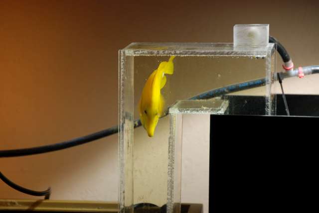
Wow that commuting tang pic is hilarous! REALLY COOL!

My kid REALLY wanted to go to the Rainforest Cafe last weekend. Honestly their saltwater tanks were in GREAT shape... the archway tank at the entrance was interesting. I told the wife (we have to get one of those). She rolled her eyes. The archway was very much like a large commuter way between the two larger sections of the tank.... thus why I brought it up ;P
 
lnzupbfbxf.jpg


Here's Tang during one of his 300 commutes a day.

Love it! I did a similar thing with one of my fresh water set ups years ago. I had a Ghost Knife that loved it.

You must not be that far from me if you got hit be the '89 quake.

Awesome build:beer:
 
I think I'm following this one.

The geek of an engineer in me says that a tank lift is simply cool. However the practical engineer in me is screaming that it is an idiotic idea and there are better access solutions. (And hopefully we can make the practical side shut up.)

On the issue of the self leveling cement. Did you touch it with anything after pouring? I always found it ironic that one of the hardest to use cements is often marketed at unskilled labour users as a time saver. It has to be mixed to insanely high tolerances, and carefully poured in a single go. And then you can't bump it for awhile.
 
Nice progress for 2 days..

Whoa... Nope. This stand took almost exactly 2 years to field!! I knew everyone would throttle me if I dragged it all along that slowly.. Your tank was a, comparatively, blisteringly fast build .

How are you connecting all of the jacks?

Each end will be welded to its neighbor. Then the top will tie the sides together.


Think you could tie the front and rear jacks together with chains/sprockets in pairs. Then tie the left and right pairs together along the back with a drive shaft of sorts. Then drive it with the motor on one end.

You have it. That is exactly the plan.


Nice work mate! Like the way u used the trailers Jack to create a stand.
Will be following the thread.

Thanks!


Im along for the show, good luck! Im interested to see what all you do with your closed loop.

Stay tuned!
 
1q56i8aqvl.jpg


Here's an unmolested jack just minding its own business...


680ii8ak5d.jpg


Standing up with the cap off.


gqsc8pzobh.jpg


Here is what the inside of the jack looks like with the cap removed and more.
I need to dump the cranks because I have to drive the jacks without a human cranking it right? I wished I could just cut off the cranks and use the end of the shafts. But if you look closely you see the cranks begin to bend the instant they clear the jack body - useless.

So on to disassembly by driving out the roll pin and then pulling the crank shaft out of the bevel gear, (the lump of grease).


ij6oef30fl.jpg


Here's the plan. Take these shafts turn them down to the metric crank size. Then key them on the English ends to use with regular gears and couplings.

Note the turned down ends.


9rpt28scxg.jpg


Here's milling the keyways in. What a pain.


u3mvsnqlyr.jpg


Test fitting a shaft.


fj9ohgr8cc.jpg


Here's a finished re-assembled jack ready to be driven. Step and repeat.

During testing it was found that if the pin backed out it locked up the jack TOTALLY. The down side of this is so huge that it's unacceptable. So I TIG'd the pins in. I had to get in and out fast to prevent damage to the gears and grease. Look closely you can see the weld in this jack.


Next up" The stand - with a problem... :hmm3::(
 
Are the photos in this thread not showing up for anyone else? I can see photos in other threads, just not this one.


As for the pins that you welded, could epoxy have been a better option if you were worried about the damage from heat?
 
I have a question regarding the jacks. Will there be some sort of locking pin?

or

Will you be depending on the teeth or cluster of teeth to hold the weight of tank. I picture some sort of differential that will allow the gears to turn the shafts in the correct rotation, but that means it is only those teeth that are meshed together supporting the entire weight. true? Scary...?
 
Are the photos in this thread not showing up for anyone else? I can see photos in other threads, just not this one.

They are hosted at box.net. See if you can get to that site form your browser.

As for the pins that you welded, could epoxy have been a better option if you were worried about the damage from heat?

No, as there is grease present, and as good as epoxy is, welds are better. :) If you saw the picture you'd see the results.


Looks good so far. Is that a zerk fitting on the jack and if so did you put it there? Its a good idea.
They are for lubing the bevel gears and ultimately the sliding and acme parts also. They came standard on the jacks but I added more since the originals appeared to be high enough to be blocked by the stand's top that drops into the jack tops. Note the picture back up farther that shows the square of steel that's welded to "bottom" of the stand's top. That is what drops into the the top of the jacks and would block the original zerk fittings. Also I need the zerks to all face into the central space unter the stand so I can access them with a grease gun.


I have a question regarding the jacks. Will there be some sort of locking pin?

or

Will you be depending on the teeth or cluster of teeth to hold the weight of tank. I picture some sort of differential that will allow the gears to turn the shafts in the correct rotation, but that means it is only those teeth that are meshed together supporting the entire weight. true? Scary...?

No. No locking pins. Well actually there are some at the bottom that let you stage the jacks as it adjusts the feet up or down. They can only be set with no weight on them.

What holds the weight up in this type of jack is a block riding on a large acme screw. NOT the crummy cast bevel gears. They only TURN the acme screw. BTW for those that don't know, there are threads for all sorts of specific uses. ACME threads are specifically designed for power transmission and hence, have very thick cross sections and shallow angles. Good for things like jacks.
So no, the gears have nothing to do with holding the weight up. I also point out that technically each jack is capable of holding up the entire weight plus 1,500lbs more so they could be made out of paper mache and it doesn't matter as their specs are clear. (4,500lbs)
 
Found the problem I was having with your images. My security program had flagged the host website as passing malware/spyware and blocked it.

I'm sure this is a dumb question, but how are you doing your plumbing? (And what is stopping you from building a stable foot stool and putting an access hatch above the tank, and skipping the movement altogether?)
 
Back
Top