You are using an out of date browser. It may not display this or other websites correctly.
You should upgrade or use an alternative browser.
You should upgrade or use an alternative browser.
LED lighting on a budget!
- Thread starter kcress
- Start date
I just built a lighting system on my tank I have a small nano tank and 40 watts on it right now going to be 50+ when im finished I need to get some more resisters but one thing I want to mention is the standard resister with stripes is gonna suck for this project if you are using the larger 10W or bigger led's.
I purchased good quality SMD High Output leds 10Watts a piece 10k, 20k whites and 460nm blues.
I also purchased a dimmer setup for leds as well and I can adjust the brightness as I wish as if it was sunrise to night.
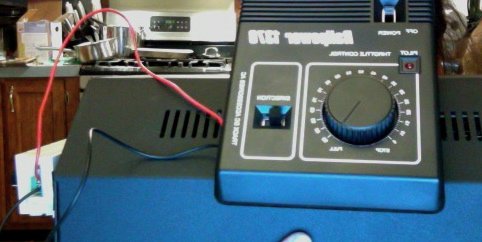
One thing I did do so I could make sure I wasnt burning out my stuff too fast is as a power source im using a train power station that is adjustable. You could do a rheostat yourself but finding them the right size for the larger leds run are a pita.
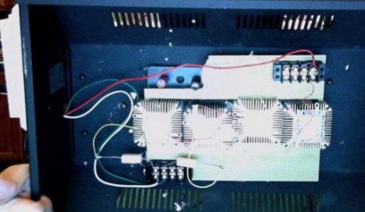
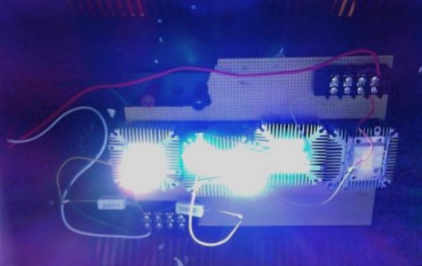
I use the ceramic rectangular resisters. and they are performing consistantly where the standard ones were not.The images Im sharing are not with it full powered I need to up the resister to a .47-1ohm @10W instead of .47ohm at 5watt. THen I should have the full range of dimming and brightness. The last 10k light isnt wired in sequence yet because I need the larger Watt resister so it will get enough power.
I purchased good quality SMD High Output leds 10Watts a piece 10k, 20k whites and 460nm blues.
I also purchased a dimmer setup for leds as well and I can adjust the brightness as I wish as if it was sunrise to night.
One thing I did do so I could make sure I wasnt burning out my stuff too fast is as a power source im using a train power station that is adjustable. You could do a rheostat yourself but finding them the right size for the larger leds run are a pita.
I use the ceramic rectangular resisters. and they are performing consistantly where the standard ones were not.The images Im sharing are not with it full powered I need to up the resister to a .47-1ohm @10W instead of .47ohm at 5watt. THen I should have the full range of dimming and brightness. The last 10k light isnt wired in sequence yet because I need the larger Watt resister so it will get enough power.
Attachments
forgive me if i overlooked something obvious here, but i cant seem to find the answer. im just trying to get 1 led working without frying my power supply. i have a 10w, 12v, 1.0a led that im trying to get set up. i can light it up with a 12v, 1.0a power supply, however it burns out the power supply in less than an hour. i read through this thread and understand that if the voltage was greater, i would have to do the math and get the correct resister. i assume that the led is pulling all the power that the power supply is supplying. therefore overworking it and burning it out. if i used a power supply that put out 12v and 1.3 a , would that be too much amps? if so, how do i use the math for a resistor if the math works out to 0 ohms? post#113 quote 5 was the closest answer i could find, but involved needing a resister if i remember correctly.
What is the actual forward voltage drop of the LED (it won't be exactly 12v), and the actual measured output of the power supply when supplying 1 A? The difference between the two should be used to calculate the value of the resistor required to ensure only 1A flows.
That said, the only safe way is to use a higher voltage supply and a constant current regulator circuit.
That said, the only safe way is to use a higher voltage supply and a constant current regulator circuit.
kcress
New member
jtec; And everyone else who's crazy enough to try to use fixed resistors.
Quit trying to calculate a resistor and use an adjustable one!
Go back to the beginning of this thread before it was run off into the weeds. Read the detailed description of how one decides what values to use. Then get an ADJUSTABLE resistor that will cover the value you you need but allows you to tweak it to where you actually need it. Using fixed resistors for these things is a fools errand.
Not sure if this has been asked before but,
I would like to keep my blue and white LED's on separate series of LED's. I have a 48v 5amp power supply that has adjustments for both voltage and current.
On the 3 xp-e Royal Blue strings I'd like to put 14 LED's with a forward voltage of 3.5v = 49v
On the 3 xl-m Cool White strings I'd like to put 14 LES's with a forward voltage of 2.9v = 40.6v
This is if the current is 5a / 6 strings = 8.33a current through each string. What impact with the difference of voltage have on all the strings. With the strings with 2.9v get more current through them? If so is this ok considering the xl-m's are actually rated for 3a?
I don't understand the relationship that different levels of total forward voltage will have on the overall voltage and current running through the parallel strings.
If I understand it correctly, when powering up the parallel circuit, the voltage will first light the CW LEDs and all of the current will flow through them (3 strings divided by a maximum of 5a = 1.6A) then as the voltage increases to where the RB strings light, the current will then be split again across all 6 strings reducing it essentially in half from the start value.
Once I have the voltage adjusted so that all of the LED's are lit when power is applied then the current should be equally distributed between all 6 strings right? Or will more current still be going into the CW strings because of the lower total forward voltage drop?
Thanks!
Last edited:
BluScrnOdeth
Darin Schmidt
Not sure if this has been asked before but,
I would like to keep my blue and white LED's on separate series of LED's. I have a 48v 5amp power supply that has adjustments for both voltage and current.
On the 3 xp-e Royal Blue strings I'd like to put 14 LED's with a forward voltage of 3.5v = 49v
On the 3 xl-m Cool White strings I'd like to put 14 LES's with a forward voltage of 2.9v = 40.6v
Your XPE string will not be 3.5V per LED because you cant supply 49V on a 48V PSU. It will be 3.43v
14xl-m, 2.9v = 40.6. If you are using a 48v PSU, you are going to need one heck of a resistor to drop the Voltage down from 48 to 40.6, unless you can run the xl-m's around 3.43V as well to make the system more efficient.
This is if the current is 5a / 6 strings = 8.33a current through each string. What impact with the difference of voltage have on all the strings. With the strings with 2.9v get more current through them? If so is this ok considering the xl-m's are actually rated for 3a?
what? you cant be running 8.33A through each string if your PSU can only supply 5A. And whatever the amps are for 1 LED is the total A's for the whole line. You only add the V's not the A's in an array.
I don't understand the relationship that different levels of total forward voltage will have on the overall voltage and current running through the parallel strings.
If I understand it correctly, when powering up the parallel circuit, the voltage will first light the CW LEDs and all of the current will flow through them (3 strings divided by a maximum of 5a = 1.6A)
No, the A's are nopt divided by how many strings you have. The Amp rating on your PSU is avalable energy. So if your string is rated at 1A, it only uses 1A, not all 5A's.
then as the voltage increases to where the RB strings light, the current will then be split again across all 6 strings reducing it essentially in half from the start value.
Once I have the voltage adjusted so that all of the LED's are lit when power is applied then the current should be equally distributed between all 6 strings right? Or will more current still be going into the CW strings because of the lower total forward voltage drop?
Thanks!
Your XPE string will not be 3.5V per LED because you cant supply 49V on a 48V PSU. It will be 3.43v
As I read the spec sheet on the HLG-240-48A, it reads that the voltage can be adjusted from 44.8 - 51.2v so I should be able to get 49 out of it no?
14xl-m, 2.9v = 40.6. If you are using a 48v PSU, you are going to need one heck of a resistor to drop the Voltage down from 48 to 40.6, unless you can run the xl-m's around 3.43V as well to make the system more efficient.
According to the XM-L spec sheet, their maximum Vf is 3.5 at 3000a. So this should be a safe voltage depending on how the HLG spreads the voltage out as the circuit is powered up.
what? you cant be running 8.33A through each string if your PSU can only supply 5A. And whatever the amps are for 1 LED is the total A's for the whole line. You only add the V's not the A's in an array.
Typo 5/6 = 0.833 so 833ma
No, the A's are nopt divided by how many strings you have. The Amp rating on your PSU is avalable energy. So if your string is rated at 1A, it only uses 1A, not all 5A's.
So based on available energy, and with all strings attached as planned. With both the voltage and current adjustments on the HLG turned all the way down The voltage available on the circuit will be 44.8v and will light the three XM-L strings using the lowest 2.5a setting on the HLG (0.833a current for each string). Then as I raise the voltage at some point the XP-Es will light and spread the available 2.5a current across the other three strings ( ~416ma). Then I can raise the current up to the maximum 5a.
My question still is when I raise the current up to 5a how will this be spread across the unbalanced strings. Will the string with lower Vf get more of the current?
BluScrnOdeth
Darin Schmidt
oh ok, i didnt know it was an adjustable voltage PSU so then yeah, you should be safe. But when reducing (unless you are having them on separate PSU's) from 49 to 40.6, thats one heck of a drop and a lot of energy going to converted into heat instead of light.
oh ok with the type, that makes way more sense lol, wasnt sure what you were getting at with the 8.3a.
The "spread" of the 5a across each string. Each array that you have made will use what it's rated at no mater how unbalanced the arrays are. as long as it can get enough amps to turn on, it will turn on. But if you have 6amps worth of arrays on the system, they will just be underpowered and may turn on if each is getting enough however, your PSU wont last very long. So, no, the lower vf will not get more current, it will only consume what it can at that Vf that its rated to (or close to it as the diagams and such arent 100% accurate).
So if I understand your comments, it would respond like this:
Strings of 14 xp-e running at 3.4v each = 47.6v this will want to draw about 800ma of current which the PSU will supply.
Strings of 14 xm-l running at 3.4v each = 47.6v this will want to draw about 3a of current which the PSU will not be able to supply (it will be adjusted to a maximum of 4.9a) so it will only draw what's available which is about 800ma.
Sound right? Still something feels missing from this explanation... Sorry not an EE or any type of electronic background.
Thanks!
BluScrnOdeth
Darin Schmidt
So if I understand your comments, it would respond like this:
Strings of 14 xp-e running at 3.4v each = 47.6v this will want to draw about 800ma of current which the PSU will supply.
Strings of 14 xm-l running at 3.4v each = 47.6v this will want to draw about 3a of current which the PSU will not be able to supply (it will be adjusted to a maximum of 4.9a) so it will only draw what's available which is about 800ma.
Sound right? Still something feels missing from this explanation... Sorry not an EE or any type of electronic background.
Thanks!
Not exactly. You have 5 amps to play with, so if one strand requires 3 and the other .8, thats a combined 3.8a. You wouldnt be able to put another string of xm-l on there because that would push you over your 5A, but you could add another xp-e putting you at 4.6A. THat puts you at 92% max usage of your PSU which i wouldnt go any higher than anyways. I try to stay around 80-85%
BluScrnOdeth
Darin Schmidt
Here is basically what the first page said but condensed.
The voltage you want for your LEDs has to add up close to the Voltage supplied by the PSU. So since yours is 47.6 that means the PSU supplies an additional .4. You will need a resistor (preferably adjustable resistor) to expell the .4v.
With the amps, its a good rule to not go over 80-85% to help increase the life of the PSU. For each array (string) you put on there, add the amps and dont go over the 80-85% (90% is as far as i would go if needed) that the PSU can supply. 85% of 5 is 4.25A.
When making an array of LEDS, their Vf needs to add up to the PSU or close to. The Amps to run them isnt addative. IF the LED at 3.5v runs at 3A, it only takes 3A to run all LEDs in the array no matter how many there are.
One other thing that helped me undertand electricity when i was younger. Since it cannot be seen running through a wire lol. .Its like a garden hose. Your wire is the hose, the water is the voltage, and the pressure behind the water is the Amps. So you need the right size hose to supply enough water and enough pressure behind it to do the job.
TheFishMan65
New member
jthuder, I think you are asking for problems, but just add a few more XML to equal the drop of the XPE. 17 should do it.
One other thing that helped me undertand electricity when i was younger. Since it cannot be seen running through a wire lol. .Its like a garden hose. Your wire is the hose, the water is the voltage, and the pressure behind the water is the Amps. So you need the right size hose to supply enough water and enough pressure behind it to do the job.
Water is the electrons, flowrate is the current and pressure is the voltage, kinks and restrictions in the hose (and also the diameter of the hose) is resistance.
Not sure if this has been asked before but,
I would like to keep my blue and white LED's on separate series of LED's. I have a 48v 5amp power supply that has adjustments for both voltage and current.
On the 3 xp-e Royal Blue strings I'd like to put 14 LED's with a forward voltage of 3.5v = 49v
On the 3 xl-m Cool White strings I'd like to put 14 LES's with a forward voltage of 2.9v = 40.6v
This is if the current is 5a / 6 strings = 8.33a current through each string. What impact with the difference of voltage have on all the strings. With the strings with 2.9v get more current through them? If so is this ok considering the xl-m's are actually rated for 3a?
I don't understand the relationship that different levels of total forward voltage will have on the overall voltage and current running through the parallel strings.
If I understand it correctly, when powering up the parallel circuit, the voltage will first light the CW LEDs and all of the current will flow through them (3 strings divided by a maximum of 5a = 1.6A) then as the voltage increases to where the RB strings light, the current will then be split again across all 6 strings reducing it essentially in half from the start value.
Once I have the voltage adjusted so that all of the LED's are lit when power is applied then the current should be equally distributed between all 6 strings right? Or will more current still be going into the CW strings because of the lower total forward voltage drop?
Thanks!
Strings with lower voltage drop will hog the current.
The amount of current for each string, will be the difference between the source voltage and the actual forward voltage drop of the string, divided by whatever resistance there happens to be in the total circuit (wire and internal resistance of the LEDs).
Hard to calculate in advance. This is why a constant current source for each string is recommended for controlling LEDs. Complex parallel strings can be hard to set up, and you'll need to use fuses to avoid destroying expensive LEDs when they get out of balance.
reefmusic, that makes more sense to me now. Lower voltage drop will hog the current. Essentially less resistance (fewer LEDs) on the string = higher current. Using the water analogy if I have a manifold with 6 parallel hoses, the hose with the least number of kinks, bends and general resistance will naturally have more flow.
This is good as the XL-Ms can handle, and will be closer to their optimal potential brightness. I can leave them a little lower for total Vf drop, just not by a wide amount.
This is good as the XL-Ms can handle, and will be closer to their optimal potential brightness. I can leave them a little lower for total Vf drop, just not by a wide amount.
Essentially less resistance (fewer LEDs) on the string = higher current. Using the water analogy if I have a manifold with 6 parallel hoses, the hose with the least number of kinks, bends and general resistance will naturally have more flow.
Yes, and because the forward voltage drop is less, the difference between that and the source voltage is greater, therefore, to continue the analogy, that string "sees" greater water pressure than the others, that combined with less kinks, ensures a lot more flow.
I've just finished this fixture today and tested it. While testing and bumped the resistor up a bit, the last LED lens melted (one LED). The LED still lights up. Have you guys experience a melted lens LED before? Other LED is still in perfect shape. I assume the heatsink compound spread poorly causing bad heat transfer so the LED overheated.
The LED is blue Cree XR-E.
The best fixture yet btw.
The LED is blue Cree XR-E.
The best fixture yet btw.
Similar threads
- Replies
- 2
- Views
- 120
- Replies
- 39
- Views
- 822