When running parallel strings, do the resistors serve a purpose other than a place to measure the strings amperage? Reading all the dozens of various threads, that is the only purpose that ever seems to be mentioned. Would the resistors also help equalize the individual strings current draw or am I barking up the wrong tree?
Fish nailed the answer. Again, yes, but not
enough to matter.
kress, thank you for the feedback - exactly what i needed to hear. I will modify things accordingly before I put it in use. Also, your assumption of the heatsink is dead on, as I am indeed using two CPU heatsinks and fans to cool the LEDs.
Your welcome and whew.. Good to hear the heat sinks are good. Maybe you should try a temp gun on the LEDs.
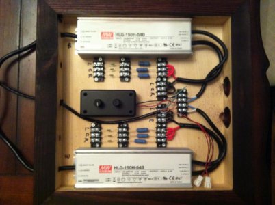
My build for my display tank is underway using 2 HLG Meanwells, that I have also mounted inside an enclosed wodden box to mount on the wall. The hinges provide a small gap around the perimeter of the door. I have two fans installed...do the same concerns apply as in this budget build?
You always have to be very mindful of electronics mounted in or around wooden boxes. How many wooden, power electronics filled appliances have you seen? :worried: There's a reason for that.:eek2:
If you're going to use wood it's best to line it with metal first. That way a roasting hot spot is going to be half or 1/3 as hot because it will necessarily conduct its heat off to the surrounding areas 'spreading the hot' to perhaps 'very warm'. And of course it's fire proof.
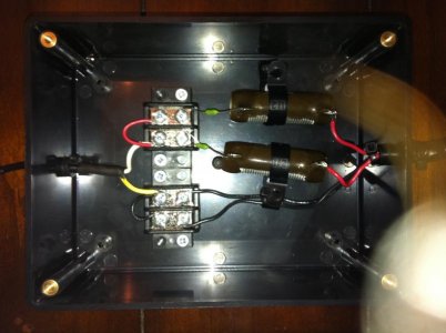
Your clean layout there will have something like 4.2W for the resistors and 2 x 60W x 0.2 = 24W call it 25Watts
You see how much heat is coming off your two boxed resistors that are dissipating 15W? Add 10W more and you will be in the ball park. Not much heat but if it's bottled up - a lot of temperature.
I'd add a fan or two. But! Fans fail. You should make sure that your setup doesn't overheat in the absence of running fans. Make sure you mount the box so convection will still occur. Mount it and run it with the fans off and the cover on. Open it and check after 5 minutes. If it seems fine check again in 30 minutes. If that's fine check in 2 hours and 4 hours. The temp should remain below hot, say about 105F anywhere on the wood. If it does you should be fine. Add your really quiet fan(s) to extend the life of the components.
Remember to use fans to extend lifetimes where needed. But use fans
and temperature switches in cases where fans are required to prevent fires. (The temp switch must turn off the equipment being cooled not the fan!)
BTW: Here's the aforementioned Bud Box type I referred to:
http://www.budind.com/view/Small+Metal+Electronics+Enclosures/Miniboxes