Looking for a specific DC CC driver for LEDs

Ok, low nanometer explains the high cost. Really though I dont think you will get a useful gain dropping below 400nm, if anything you up the risk to your eyes when you accidently look at them and don't really get much PAR of use to the coral when dropping below 420nm.

the glowing black light effect yes, but is it worth the high cost to go that low on the nanometer scale? In my experience no, but if that is the look you are after then go for it.

In my experience that type multichip are pretty low efficiency, mostly due to thermal management issues internally, not that great of quality control a lot of the time. Heat won't be a concern for your intended setup but just know that the efficiency of the dies used in most of those is sub par as compared to the better bins used in things like the single die semi packages.......now if you could get your hands on those in a big multichip.......and know the bin of the dies, that's a different story.....

Now that I see you are after uv though not many other options out there for higher power, 4ups in the luxeon M styling are the biggest I've seen readily available, though semi makes some bigger packages, never seen them offered anywhere.

although someone like steves leds could solder you up a multichip array if you can find the pcb off ebay (or sourced from a highher quality board house ideally) using his good violet chips and I think you'd be better off going that route, just my two cents.
 
So here's my findings on using royal blue, 395nm and 365nm single stars ...

The royal blue is "cosmetic" color but also contributes to enough PAR to generate growth.

The 395nm gives a very dramatic"cosmetic" pop, a little growth benefit, but less than the RB. But it also contributes to a real color change of the coral tissue. So, if you grow two identical frags, one with this light vs. another without, then compare both under the same MH light, the frag growing under 395 will have a real color change.

The 365 gives the most intense "blacklight" pop, but very little growth benefits. It also has the most impactful real color change.

If I could create a table, I could make this much clearer.
 
Ok, low nanometer explains the high cost. Really though I dont think you will get a useful gain dropping below 400nm, if anything you up the risk to your eyes when you accidently look at them and don't really get much PAR of use to the coral when dropping below 420nm.

the glowing black light effect yes, but is it worth the high cost to go that low on the nanometer scale? In my experience no, but if that is the look you are after then go for it.

In my experience that type multichip are pretty low efficiency, mostly due to thermal management issues internally, not that great of quality control a lot of the time. Heat won't be a concern for your intended setup but just know that the efficiency of the dies used in most of those is sub par as compared to the better bins used in things like the single die semi packages.......now if you could get your hands on those in a big multichip.......and know the bin of the dies, that's a different story.....

Now that I see you are after uv though not many other options out there for higher power, 4ups in the luxeon M styling are the biggest I've seen readily available, though semi makes some bigger packages, never seen them offered anywhere.

although someone like steves leds could solder you up a multichip array if you can find the pcb off ebay (or sourced from a highher quality board house ideally) using his good violet chips and I think you'd be better off going that route, just my two cents.

These chips have to be close to 1" (25mm). The 40mm x 40mm is already much much larger than I would prefer. There's no room for a PCB horizontally. The thermal attachment to the liquid cooled aluminum fixture is key. I don't think a PCB would do the job vertically either without a lot of copper.

These have to be as bright as possible but have the smallest cross-sectional area possible.

Also, the power conversion I'm working on is a lot more efficient than traditional AC-input drivers, and most of my PAR is sunlight driven. My biggest concern is color (reflected, fluoresced, and absorbed into tissue recoloring).
 
Yikes - the price jumped to $225 on the ones I was looking at.


I found it from another vendor.


http://www.ebay.com/itm/UV-LED-10W-...hash=item3d0deb00c6:m:mPOaZTw4E4SCAdbgk6rco3A


Price varies dramatically depending on wavelength and power:

100W @ 365nm = $182

100W @ 395nm = $54


The very high frequency LEDs are not manufactured on the same lines as the cheap $9.99 white multi-chips. They wouldn't even pass test.


But to test my setup, I'm getting 100W $2 multi-chips - these are disposable and intended for testing and PAR reference only.


Here's the one I was looking at before-

http://www.ebay.com/itm/100W-100-Wa...345954?hash=item35df2a1da2:g:v2AAAOSwAYtWLzrv


These chips usually go into UV vision inspection equipment or UV cure industrial machines. They just happen to have the desired frequency for my supplemental effect. The raw materials are in short supply and the number of manufacturers who can build it is limited. So - the supply is usually from the same suppliers.


In any case, I'm going to measure PAR on every chip I get and run at least a 170hr burn-in and PAR re-test.


I also found this - I think the guy I was emailing at Sure has posted 20x of the buck converters based on my exchange with him - Only $5 a piece.

http://www.ebay.com/itm/20pcs-300-3...879603?hash=item2a4dbd52f3:g:wRUAAOSwo8hTopLs


HA HA HA HA


Still concerned that inductor will not just simply core saturate at the 3A mark or before. Feels awfully small for a properly rated 22uH :-/

Only one way to find out I guess :)
 
And the low frequency UV dies are mondo expensive, rare, and inefficient (relative to the sweet spot of 450nm for current technology) as you pointed out. This build is many levels of exciting
 
And the low frequency UV dies are mondo expensive, rare, and inefficient (relative to the sweet spot of 450nm for current technology) as you pointed out. This build is many levels of exciting

I think you mean low wavelength, high frequency - and yes!! They are industrial use so far, so not a lot of consumption.

After I've done some testing, I'll start a build thread on my fixture and liquid cooling.

The 450nm blue is very nice by the way. It's a very good way to find balance in color viewed, color grown, and PAR growth... I'm going to have a mix of doubles (UV, RB ----- UV, RB ----- ...)

I started with actinic fluorescents back in the 80s and 90s. They weren't UV only - those were blacklights. They weren't RB only either. They were a blend of both. The RB LEDs today don't match my VHO actinics in the 90s. They may grow corals better, but it's just not the right mix.

This is my attempt to bring that old rebalance of the three primary light benefits into an ultra-high density light source.
 
I thought it was 380 which is why I was tending towards the 395nm.

http://www.advancedaquarist.com/2014/5/aafeature

Some excerpts:

<a href="http://s1062.photobucket.com/user/karimwassef/media/0_zpswgaq2t61.png.html" target="_blank"><img src="http://i1062.photobucket.com/albums/t496/karimwassef/0_zpswgaq2t61.png" border="0" alt=" photo 0_zpswgaq2t61.png"/></a>

I'll tell you what I get (or if I get) :)

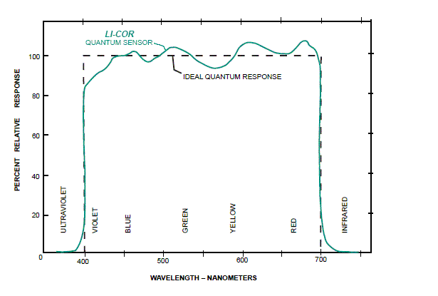
Love this chart

image_full
 
Last edited:
At 395, I'll multiply by 2.

I did post the article so I know what Dana says in it.

Back to my driver. I should have the DCDC power supplies in two weeks.
 
ok. I got them

<a href="http://s1062.photobucket.com/user/karimwassef/media/2078C5FF-D406-44B7-887D-C9CD5F4008BC_zpsenumpymr.jpg.html" target="_blank"><img src="http://i1062.photobucket.com/albums/t496/karimwassef/2078C5FF-D406-44B7-887D-C9CD5F4008BC_zpsenumpymr.jpg" border="0" alt=" photo 2078C5FF-D406-44B7-887D-C9CD5F4008BC_zpsenumpymr.jpg"/></a>

along with an ultracheap 100W RB LED.. to experiment

They looks well made enough

<a href="http://s1062.photobucket.com/user/karimwassef/media/A001CC63-4324-4563-B37D-5615A36B5167_zpshlvhfqvk.jpg.html" target="_blank"><img src="http://i1062.photobucket.com/albums/t496/karimwassef/A001CC63-4324-4563-B37D-5615A36B5167_zpshlvhfqvk.jpg" border="0" alt=" photo A001CC63-4324-4563-B37D-5615A36B5167_zpshlvhfqvk.jpg"/></a>

<a href="http://s1062.photobucket.com/user/karimwassef/media/5F9ED2BF-3B25-442B-BEB6-365247D03EE4_zpsobanyncl.jpg.html" target="_blank"><img src="http://i1062.photobucket.com/albums/t496/karimwassef/5F9ED2BF-3B25-442B-BEB6-365247D03EE4_zpsobanyncl.jpg" border="0" alt=" photo 5F9ED2BF-3B25-442B-BEB6-365247D03EE4_zpsobanyncl.jpg"/></a>

well, the power supplies anyway. The LED looks roughed up - shipped in a bubble envelope only.

<a href="http://s1062.photobucket.com/user/karimwassef/media/FB3660A0-D959-43D4-B0B6-B5D90C8739C7_zpsoy5onbny.jpg.html" target="_blank"><img src="http://i1062.photobucket.com/albums/t496/karimwassef/FB3660A0-D959-43D4-B0B6-B5D90C8739C7_zpsoy5onbny.jpg" border="0" alt=" photo FB3660A0-D959-43D4-B0B6-B5D90C8739C7_zpsoy5onbny.jpg"/></a>

Here's a close up

<a href="http://s1062.photobucket.com/user/karimwassef/media/FF5D1D4C-88C1-4439-BD9E-7051C9818A52_zpsigryq4dz.jpg.html" target="_blank"><img src="http://i1062.photobucket.com/albums/t496/karimwassef/FF5D1D4C-88C1-4439-BD9E-7051C9818A52_zpsigryq4dz.jpg" border="0" alt=" photo FF5D1D4C-88C1-4439-BD9E-7051C9818A52_zpsigryq4dz.jpg"/></a>

So.. no documentation either. Here's the site

http://store3.sure-electronics.com/ps-sp12153

It says:

300-3000mA Buck Regulator LED Driver for 1-100W High Power LED

Brief Introduction:
Welcome to use LED driver series by Sure Electronics.

This product is constant current and step-down DC/DC converter.

Featuring under voltage lock out (UVLO), over temperature protection, LED open-circuited protection and LED short-circuited protection.

This driver features small size, high efficiency, stability, long service time and easy installation.

LED dimming can be controlled via an extra pulse width modulation (PWM) through EN pin.

Features:
Minimized size, high efficiency
Constant current output, stable LED lighting
Input voltage: 10V-45V
Full protection: Thermal/UVLO(Under Voltage Lock Out)/Start-Up/LED Open-/Short- Circuit
Easy installation and long service life
Under voltage protection voltage:9.6V
10,000:1 PWM Dimming Range
250:1 Analog Dimming Range
Built-in soft-start function

Applications:
Signage and Decorative LED Lighting
Automotive LED Lighting
High Power LED Lighting
Constant Current Source

Port Definition:
Pin:Description
VIN:Positive terminal for 10V -45V DC Power supply
GND:Power Ground
LED+:Positive of LED terminal
LED-:Negative of LED terminal
EN :PWM terminal. When applied with ground or suspended, full amount of current will be output and when connected with +5v or VIN, output current will be 0.

Specification:
The typical parameters are listed in the table below.
Tested @ Vin=24V, 4 Luxeon White LEDs connected in series, tem 18℃ (unless noted otherwise)

Parameters(Test Condition).........................................Min./Typ./Max.
Supply Voltage..................................................................10/-/45V
Supply Current (no load)(Vin=10V~60V).............................-/2/5mA
Output Current (Iout).......................................................150/-/3000mA
Accuracy.............................................................................-/±3/±10%
Efficiency (Vin=24V, 4LEDs).................................................-/96/-%
Input Voltage (EN)* High Potential ....................................3.5/-/Vin V
Input Voltage (EN)* Low Potential ........................................-/-/0.5V
Minimum Turn-on Time......................................................-/110/150ns
Minimum Closing Time*.....................................................-/110/150ns
Over Temperature Protection*.......................................145/165/175℃
Over Temperature Protection Hysteretic State*..................20/25/40℃

Note: * from Data Sheet of LM3409 chip. Please refer to the relevant documents for the details.

and then a mechanical drawing and package contents.

So. I'm feeding it with 36VDC. Need 3000mA.
I'm going to setup my Arduino Mega to generate a 5V PWM pulse at 50% duty cycle at a frequency of ~ 1KHz (16MHz/64/255).

Ok... the confusing part is the connection matrix on the bottom, showing 8 pins in a 2 x 4 formation.

The four stack have different mA : 300mA / 600 mA / 900mA / 1200mA

So the total is 3000mA. I'm guessing that's a current limit jumper stack?

I'll email - but what do you guys think?
 
If it works anything like their other drivers, adding more resistors to the circuit in parallel (lowering the resistance) ups the output current, so with all of them selected that should give you 3000mA roughly, and I'm guessing with none selected it outputs 150mA.
 
Oh I see.

The series of resistors above can be selected in or out based on jumpers? There's 4x6 resistors and 4x4 options so two sets must be always in to set the default.
 
Is doesn't say that anywhere. So I assumed no jumpers = 3000mA current limit?

It is a current limit matrix then?

Yes, the jumper matrix allows selecting a range of output current, making the driver more versitile. Fire it up and find out, it works on of two ways, adding resistance increases current, or reducing resistance increases current.

The way they have it labeled and the way their smaller drivers work makes me think the latter.

As you've probably figured out their documentation isn't that good.
 
Back
Top