Meanwell LDD driver: for those who want to dim to 0 using Arduino

Hey guys,

First of all, Awesome discussion and great work by rrasco and O2Surplus! I've been creepin' around this thread quietly for some time now and thought I'd chime in.

rrasco and O2: What about connecting the CTRL/PWM pin of the driver to the ground plane via an optional 10K pull-down resistor? This will pull the pin voltage to ground if the PWM signal is ever lost, which will prevent the driver from failing high (and will instead fail off)? Basically you just need to create a trace with a spot for a resistor to connect to the ground plane. For people without controllers you'd just leave this spot empty; for people with controllers, adding a 10K resistor will add at most 1mA draw per PWM signal to your controller and have the added safety of having the lights fail off.

Just you wait until you're on vacation and the fishsitter accidentally tugs on the PWM cable and you come home to find your LEDs have been on at 100% for a week straight! A few $0.02 resistors could save you thousands in livestock.

My other question to the community: Does anyone have an extra 4-up LDD-H 10cmx5cm board that they could part with? Please PM me if you do! I just need one.

Cheers,

Kevin

I think this is a good idea, I'm going to add resistors to mine, if I unplug my arduino my drivers go full blast
 
Sorry, probably a stupid question but I'll pose it anyway, gotta learn somehow right :)

I love this idea, but the electrical engineering of it escapes me, at least this late at night. if the drivers are turned off by connecting the pwm pin to ground wont the resistor keep them turned off all the time? isn't that basically how the typon controls them, by switching a ground path on and off really, really fast via a transistor?

This will help...

Pull-downresistor_zpsbfb95e1c.png


When the PWM controller (be it Typhon or other) applies a signal to the PWM pin of the driver (for the sake of argument, let's say 10V), there is also a 10V drop across the resistor to ground since the driver and resistor are connected in parallel. If you use a high value resistor (again, let's say 10K ohm), at a 100% signal (Full on) there will be at most 1 mA flowing through the resistor to ground. The driver still only sees 10V as it is unaffected by the presence of the resistor. You controller will feel the extra 1 mA per PWM signal, but that is minimal and the current decreases linearly with the PWM duty cycle. So nothing changes in normal operation.

Where it comes into play is when you unplug the controller from the drivers. If the PWM pin of the driver is left floating or open, the driver defaults to 100%. By adding the resistor between the PWM pin and ground, the PWM pin is now connected only to ground and so the pin voltage gets pulled to ground when the controller is disconnected. Thus the driver defaults off.
 
So, is there a way to hack the existing design to incorporate the resistor - my boards have already been ordered...
 
So, is there a way to hack the existing design to incorporate the resistor - my boards have already been ordered...

You can hack the original design quite easily by adding a 10k ohm resistor anywhere along the PWM trace. The easiest way would be to use a conventional "through hole" resistor. Solder one end to the PWM pin and the other to the VCC negative pin at each LDD. I'm using SMD (M1206) resistors and will use the same procedure as described above but with a slight twist. I'll solder one end of the resistor directly to the PWM pin pad and then scratch the coating off of the PCB near the other end of the resistor. This "scratch" will expose the ground plane of the PCB. Add a little flux, apply some solder and I'll be done. "Easy as pie"
 
I'll be adding the default-off to my setup, assuming I can't figure out a way to do it with the board I'm using to control them. Good ideas still going in this thread!
 
neoferdina, thanks for the explanation. Makes sense now. I had forgotten that arduino based circuts output a current to the pwm pin. I think I was staring at a one of the manual dimmers for 12 volt lighting last night.
 
The resistor idea is a good one. Will the driver ever be truly 'off' when powered, or does the pull-down resistor give it ever-so-little power that it's really on, just not much? As opposed to 100%? That's what I would expect it to do anyways.

I'll spare you the elaborate technical explanation (I can go into the details if you wish) but: No, it's not an issue.


I have a question to everyone else using these drivers right now...

I know this has been asked a couple of times through out the thread but there hasn't really been a definitive answer:

Do these drivers run cool enough to be kept in an enclosure? Or is it necessary to add perforations to the enclosure lid?

I'm planning on integrating my PSU, driver and Typhon controller into one enclosure and ideally I would like to keep my set up water tight (after all it will be sitting right next to a lot of water). If you don't think that will fly, would adding perforations to the enclosure over the drivers suffice or do I need to add active cooling?

Free air convection cooling. In essence, no they don't need holes. Of course, that will deal more with your environment. I have been running two of them in an enclosed fixture with only passive cooling. My fixture gets warm to the touch, but that's from the LEDs.
 
The resistor idea is a good one. Will the driver ever be truly 'off' when powered, or does the pull-down resistor give it ever-so-little power that it's really on, just not much? As opposed to 100%? That's what I would expect it to do anyways.

If the signal to the PWM pin is 0%, then the output will be 0%. The resistor won't change this as it is connected to ground and thus there is no potential for the resistor to apply to the PWM pin. In fact, the resistor is more likely to give you a true 0% output than your controller.

Free air convection cooling. In essence, no they don't need holes. Of course, that will deal more with your environment. I have been running two of them in an enclosed fixture with only passive cooling. My fixture gets warm to the touch, but that's from the LEDs.

The plan was to put the drivers, supply and controller into a waterproof enclosure that I have. It's a nice, clear polycarbonate enclosure so you get to see all the wonderful science inside :strooper:. I'll be machining the top of the enclosure for the LCD screen to fit through and for access to the buttons. It'll be fairly fit inside of the enclosure. Not packed, but full. So I've a little concerned how hot it might get.

I may just try it and see. I can always put some fancy decorative perforations in after if it gets too hot.
 
In thinking about the on/off situation if the controller is disabled, it may be better to leave things like they are and just put the power supply on a timer to turn on 5 minutes before the leds start and turn off 5 minutes after they are scheduled to turn off.

This has two advantages:

- the power supply will be completely powered down when not needed
- the leds will still turn on/off generally in line with the normal operating times with the only thing missing being the dimming.

Coming back after being away with the lights off might be just as bad as them being on.
 
that does not fix it for me, I run my leds at 30-70 % depending ont he channel, if my controller is unplugged then they all go to 100 % without a pulldown resistor
 
Did anyone ever figure out if these LDD's work with Stevesleds ATMega328 based "Aquarium Controller Interface" which converts 0-10V analog from an Apex or ReefKeeper into PWM signals?

Seems like it should work, but it seems like he'd mostly make it work with his drivers which are described as:

Accurate linear dimming is compatible with PWM frequencies from 100 Hz to 5 kHz for PWM duty cycle down to 1%. PWM frequencies up to 50 kHz can be supported for duty cycles greater than 10%.

and I know these LDD drivers only accept PWM input up to 1kHz, so if his aquarium controllers are putting out up to 5kHz, that's no good for these LDD's.

also, think someone could put in a couple of through-holes into the traces on either the rrasco 4-up or the O2Surplus 5-up for those pull down resistors? Then they could be optionally added if someone cared for them to fail off with no PWM input or they could be ignored if you didn't feel like adding the resistors. Or am I understanding it wrong?
 
Also, to connect the LDD to the board, would something like:

part 310-93-110-41-001000 from http://www.mouser.com/ds/2/273/073N-58368.pdf

work to just snip a few off the strip and solder them to the board for the LDD to plug into or would the full 24-pin block earlier be cheaper and easier?

Those interconnects may work just fine, assuming they match the dimensions needed by the pins on the LDD. Personally, I'll be using the chip holders shown in previous posts, as they're perfectly suited to do the job and can be purchased for little $$.
As for PWM dimming- the Steve's interface module can handle a range of PWM frequencies that includes the usable PWM frequency for an LDD.
 
Last edited:
The plan was to put the drivers, supply and controller into a waterproof enclosure that I have. It's a nice, clear polycarbonate enclosure so you get to see all the wonderful science inside :strooper:. I'll be machining the top of the enclosure for the LCD screen to fit through and for access to the buttons. It'll be fairly fit inside of the enclosure. Not packed, but full. So I've a little concerned how hot it might get.

I may just try it and see. I can always put some fancy decorative perforations in after if it gets too hot.

Pictures Please ! :)
 
Those interconnects may work just fine, assuming they match the dimensions needed by the pins on the LDD. Personally, I'll be using the chip holders shown in previous posts, as they're perfectly suited to do the job and can be purchased for little $$.
As for PWM dimming- the Steve's interface module can handle a range of PWM frequencies that includes the usable PWM frequency for an LDD.

Thanks. I looked at the data sheet for the LDD and its obvious that they were designed for one of those chip holders. The pins are even numbered for it on the data sheet. They're like $1 in quantities of 10 from mouser.

Ok on the interface module, just hadn't seen someone report back that it did indeed work.

Funny how the custom made boards end up costing less than off the shelf plastic terminal bars and sockets.
 
Did anyone ever figure out if these LDD's work with Stevesleds ATMega328 based "Aquarium Controller Interface" which converts 0-10V analog from an Apex or ReefKeeper into PWM signals?

Seems like it should work, but it seems like he'd mostly make it work with his drivers which are described as:


and I know these LDD drivers only accept PWM input up to 1kHz, so if his aquarium controllers are putting out up to 5kHz, that's no good for these LDD's.

I have the Aquarium controller interface from Steves led. I am currently having problems with after my apex neptune goes to 0 volts the leds still are lit up slightly.
 
I have the Aquarium controller interface from Steves led. I am currently having problems with after my apex neptune goes to 0 volts the leds still are lit up slightly.

Can you measure the voltage that is on the apex output to see if its really 0? Maybe you have some stray. If that is 0 then does Steve's interface still leave them on dimly if you totally remove it from the apex output (which should guarantee 0v from apex, heh)? If theyre still on dimly then maybe try to remove Steve's interface output from the pwm pin on the LDD and put that pin to ground which should guarantee no signal on there and see if they're still dim.
If so, you have a short somewhere, I guess.
 
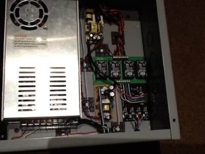
I have tried taking out the input from the apex into the aquarium controller and still the LEDs are lit dimly. I am starting to wonder if its the way I am powering the aquarium controller. I have a 5 volt wall wart to power it. I have the wall wart hooked up to the 5 volt input in the aquarium controller and the negative side of the wall wart going to the vin- of the ldd board from rrasco. I also have the ground from the aquarium controller going to the same vin- on the ldd board.

Any suggestions?
 

Attachments

  • image.jpg
    image.jpg
    58.2 KB · Views: 8
Neoferdina, IMHO I would not put these in an enclosed box. Rrasco said convection cooling and you won't get that in an enclosed box. Perforated holes might be enough. I just finished reading the whole thread and nobody really said how the behave temperature wise. Rrasco said not to hot, but earlier it was stated they run hot. I think it depends on how much voltage is being dropped. Anybody have any number for temperature at different voltage drops across the LDDs?
 
Back
Top