Driving LEDs at their peak current is really not a great idea. As you approach the top, there is not really that much more light. Also do you realize that when LED emitter gets hotter it's light output is reduced? If you don't have ideal cooling, then you are just wasting both electricity and the life of your LEDs.
You are using an out of date browser. It may not display this or other websites correctly.
You should upgrade or use an alternative browser.
You should upgrade or use an alternative browser.
Meanwell LDD driver: for those who want to dim to 0 using Arduino
- Thread starter pwreef
- Start date
megadeth72
New member
have cooling taken care of, 1200ma would probably be ok, I dont want to run at peak, I need 3 that can do that, and the other 2 can be 1000ma drivers
megadeth72
New member
I'll take that under consideration, I ran a 400w halide over a 20g tank for years, did not kill corals
specs on the led I'm using
60cm air par
700ma = 332 par
1000ma = 486 par
1400ma = 563 par
specs on the led I'm using
60cm air par
700ma = 332 par
1000ma = 486 par
1400ma = 563 par
Yup its not possible to kill anything with MH because the light spreads out. Put some XM-L or XT-E with 60 degree lenses and you will be bleaching corals left and right. With LEDs its possible to create light that will be even stronger than natural sunlight and cook everything in your tank.
megadeth72
New member
milliamps does not mean much unless you clarify what it's going into, personally I've not been impressed with 1 or 3w leds even with lenses, and with 60 the disco is pretty bad unless you mount it high, then the par drops quick. They spread the light out more like vho/pc's, I prefer point source like halide/pendants, with high/hot spots in the tank, just place corals accordingly
par numbers are with my uncalibrated DIY par meter, so subject to change, but for comparison of my own lights it works fine
3 lights I just tested
12x3w 10k bridgelux on my planted tank 60 degree lens, these are 3.7V @700mA chips
50x1 multichip 10-14k ebay special on reef 62 degree lens these are 32-34v @ 1500mA
marineland 18-24 doublebright piece of crap that came with tank
on air the 12x3w is putting out 85 par at 24" using 10k leds the heatsink is a big aluminum thing with a fan, it runs 80 degrees
on air the 50x1w multichip is putting out 220par at 24" it's a 12-14k array the emitter runs 92 degrees at max, and it's using a P4 cpu heatsink
on air the marineland put out 20 par at 24"
I run all of mine at 100 % capacity, I'm not worried about life, and the temps are so low compared to what these can withstand, it's just not a concern of mine
Last edited:
just had 11 ldd-700's show up today (since that's the max current for my bridgelux led's... besides not many people even run cree's past that)
The LED's are in the mail, waiting on some protoboards... got a null modem cable and some pcb mount connectors, some 10 pole screw terminals, and a 48v 350w power supply.
Hope at least the pcb's show up tomorrow, can get the control boards built and waiting for the led's
The LED's are in the mail, waiting on some protoboards... got a null modem cable and some pcb mount connectors, some 10 pole screw terminals, and a 48v 350w power supply.
Hope at least the pcb's show up tomorrow, can get the control boards built and waiting for the led's
rrasco
Active member
Over my 105 I am running two arrays of 36 LEDs each with 60* optics. They are bridgelux 3w varying in color from 4500K, 6500K, 10000K, RB, and Pink. Running them off CAT4101 set with a resistor to limit current to 700mA, their max. I am running whites at 50% and blues (and pink, only 2 per array) at 55%. So 350mA and 385mA respectively. Whites to blues is 2:1. They are 10" AWL on a 21" deep tank.
When I had access to a par meter, I didn't have any optics. They were the 'built-in' optics. At the time, I was getting pretty bad numbers. Ranging from 50-80 at the sand and only about 150-200 at water level. I added 60* optics the next week but unfortunately have not been able to borrow another meter yet. The tank got about 3x brighter though, and it's supporting everything including SPS.
I had the lights running at 45% and 50%, tried bumping them up to 55% and 60%, and it starting bleaching corals. Dropped them back down 5% and am still recovering from that mishap. So basically what I am saying is, be careful with LEDs. What works for one might not work for another, based on tons of variables, especially in DIY systems.
PWM- goes to Vin- , PWM+ goes to the DIM pin. This is common design practice not to create extra solder points.
I don't quite understand this. Vin- and Vi+ are not supposed to be hooked to the power supply? Do you connect the Vin- pin of the LDD both to the negative of the power supply and the negative of the controller PWM-?
rrasco
Active member
I don't quite understand this. Vin- and Vi+ are not supposed to be hooked to the power supply? Do you connect the Vin- pin of the LDD both to the negative of the power supply and the negative of the controller PWM-?
Sounds about right. They can share a common ground. My PWM signals are always 1 pin from the microcontroller though, so I've never seen this setup before. Ground is a ground though, normally, just not on the output side of the LDD.
rrasco
Active member
rrasco
Active member
I didn't find it difficult, but that will depend on your soldering experience.
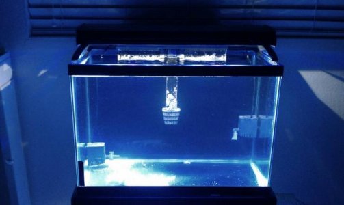
FWIW, I put a lead on the PWM pin, but didn't connect anything to it so I am running them at max (of the driver) which is 600mA, so they are at 85% of the emitter's max. I am working on another project for a DIY arduino that is fairly cheap, so I might control them via that at a later date. For now, this works with a timer.
I am not running them with optics so I don't kill anything over this small tank.
I'm glad to hear that. I had read that it was pretty tricky and that is why I'm very interested in how to mount them in a protoboard. If soldering the wires is not very difficult then they can be placed almost anywhere.
I'm curious about the dimming when you build the arduino.
Congratulations for the setup and the nice tank
I'm curious about the dimming when you build the arduino.
Congratulations for the setup and the nice tank
megadeth72
New member
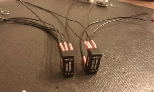
helping hands aligator clips make it easy
")
rrasco
Active member
I already have the code written that's running my current tank. Parts of it were pulled from sources here, then I customized it for my current setup. I'm going to strip out all the LCD code and extra stuff and just run the dimming program by itself. It's an atmega328 so I can program it in an arduino and pull the chip. Hopefully this batch of PCBs works though. Still waiting for them to show up.
Similar threads
- Replies
- 3
- Views
- 2K
- Replies
- 46
- Views
- 13K