Meanwell LDD driver: for those who want to dim to 0 using Arduino

I looked at the jarduino but I'm going to go ethernet on mine... I actually don't want an lcd display sitting around and would rather be web enabled at all times (run multiple monitors so I can see it on there, and set up sms messages for problems)

the lights and web programming will be phase 1 of it... once I have that all working I'll move onto outlet controls and various other goodies. be a long ongoing project that's for sure
 
If you want internet-enabled, look at the linksprite diamondback, its an arduino clone with wifi baked into the board. It's a little more expensive, but adding ethernet always is.
 
The author of the jarduino is looking to eventually implement wifi/smartphone access in the next version.

I'm good with just the lcd sliders, since the wifi board cost more than the whole arduino kit itself, but android control would be really cool.
 
I got an ethernet shield off of ebay for 9 bucks, it showed up today so I've begun tinkering with it.

I'm just planning some light webpages so that you can access it form pc, smartphone, tablet, yadda yadda
 
Ah, well, yeah, wired ethernet will be cheaper. I wanted wifi so I didn't have to run a drop to my fish room.
 
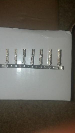
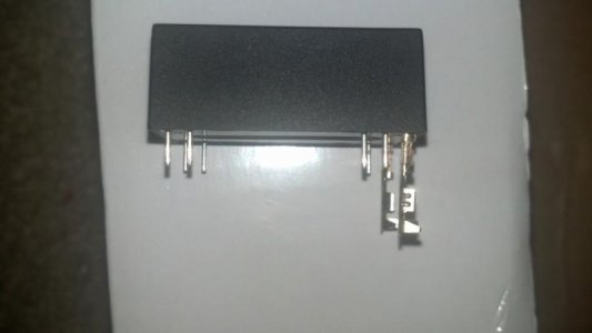
These are a great option so you dont have to solder onto the pin themselves. They fit very tight on the LDD pins and you can either solder the wire to the end of these or just crimp the wire
 

Attachments

  • 2012-11-18_01-36-31_284.jpg
    2012-11-18_01-36-31_284.jpg
    21.8 KB · Views: 9
  • 2012-11-18_01-37-42_926.jpg
    2012-11-18_01-37-42_926.jpg
    20.4 KB · Views: 10
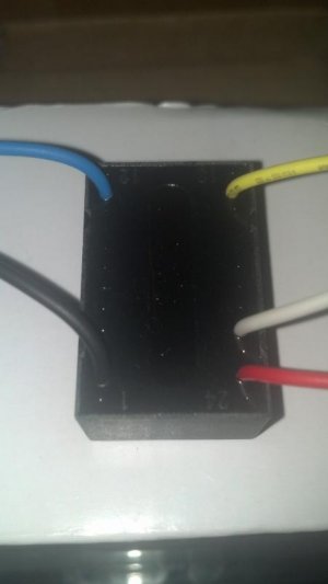
This is how the LDD's look when you buy the ones that are already wired, less "pins" and so much easier
 

Attachments

  • 2012-11-18_13-10-45_658.jpg
    2012-11-18_13-10-45_658.jpg
    19.8 KB · Views: 10
I know how many pins they have, I've used these drivers, which is why I was confused about the picture posted with the pins crimped.

I would have bought the LDD-xxxLW but Mouser didn't have any in stock so I had to make my own leads. Maybe in the future I'll actually PCB mount them.
 
I picked up some cheapo PCB's from ebay when I was buying connectors and what not too. I'm mainly just waiting on my screw terminals to show up so I can easily connect my strings to this driver setup, put it in a box and I'm good to go
 
Hi guys, I brought some 700h and a 1000h. I soldered them on a diy pcb so I created a slim power shield that is connected to my Arduino2560. My problem is that the Arduino don't dim the channels and the leds go to full power.
Have you encountered the same problem?
 
There could be a lot of things wrong here. Mis-wiring or software issues. We are getting into complex machinery here. Its not a light bulb with dimmer anymore.:spin1: Need more details on how you have everything wired and programmed.
 
Hi guys, I brought some 700h and a 1000h. I soldered them on a diy pcb so I created a slim power shield that is connected to my Arduino2560. My problem is that the Arduino don't dim the channels and the leds go to full power.
Have you encountered the same problem?
I ran into that problem a couple days ago. I have four 1000H, two 700H and a 300H on protoboards mounted inside my fixture. Power comes from a Mean Well SP-200-48 and control from my Reef Angel, both mounted in my stand. There is a piece of lamp cord connecting the power supply to a pair of binding posts on the back of the fixture and a piece of Cat 5 plugs into the fixture to control the 4 channels. when I first set it up the white channel on one heat sink and the RB on the other heatsink would not dim. I did a lot of troubleshooting before I figured out that my conections at the data cable jack were the problem. If you get signal to the driver, it will dim. If it doesn't dim, find out why it's not getting the signal.
Of course, the following night I was cursing the LDD's for dimming all the way to zero. It seems that my white channel went down to 1 instead of zero and I had 20 LEDs that I could not shut off. You'd be surprised by how much light you get from 20 LEDs at 1%! Roberto at Reef Angel helped me out by supplying a few lines of code. It looks like it was a floating decimal point error when the unit had calculated the parabola for sunrise/sunset.
Everything works well now and I'm quite happy that I went with the LDD's. I really have to praise Reef Angel. They been great with their support, not only with the issue above, but also in setting me up with a 5v version of the PWM expansion module. There's a little more fine tuning to be done but I'm thrilled with how this project turned out.
 
I used a Typhon sketch modified to run on Mega2560. It works in all functions I tested... except dimming! :D
When the wire is disconnected, leds go at 700mA, but when I connect it, leds start flashing very fast, but I see the same light... it seems more a disturb on the line. I'm thinking that it can be a problem of the PWM frequencies, how can I test the exit value of the Arduino?
 
the meanwell needs a 100-1000 htz pwm

arduino pwm frequency can be adjusted, and different pins use different default frequency setups, but I thought all were within the 100-1000 range, what pin are you using on your mega?

you can get oscilloscopes for under 100 $ now, you can even get a nano quad channel for 175 $
 
Back
Top