You are using an out of date browser. It may not display this or other websites correctly.
You should upgrade or use an alternative browser.
You should upgrade or use an alternative browser.
Meanwell LDD driver: for those who want to dim to 0 using Arduino
- Thread starter pwreef
- Start date
bhazard451
New member
I ran into that problem a couple days ago. I have four 1000H, two 700H and a 300H on protoboards mounted inside my fixture. Power comes from a Mean Well SP-200-48 and control from my Reef Angel, both mounted in my stand. There is a piece of lamp cord connecting the power supply to a pair of binding posts on the back of the fixture and a piece of Cat 5 plugs into the fixture to control the 4 channels. when I first set it up the white channel on one heat sink and the RB on the other heatsink would not dim. I did a lot of troubleshooting before I figured out that my conections at the data cable jack were the problem. If you get signal to the driver, it will dim. If it doesn't dim, find out why it's not getting the signal.
Of course, the following night I was cursing the LDD's for dimming all the way to zero. It seems that my white channel went down to 1 instead of zero and I had 20 LEDs that I could not shut off. You'd be surprised by how much light you get from 20 LEDs at 1%! Roberto at Reef Angel helped me out by supplying a few lines of code. It looks like it was a floating decimal point error when the unit had calculated the parabola for sunrise/sunset.
Everything works well now and I'm quite happy that I went with the LDD's. I really have to praise Reef Angel. They been great with their support, not only with the issue above, but also in setting me up with a 5v version of the PWM expansion module. There's a little more fine tuning to be done but I'm thrilled with how this project turned out.
Pics!
Dave Thebrewguy
New member
I'll work on pics. I haven't had to host a photo anywhere in years, other forums I've been on over the years have allowed direct uploading of photos so I've got to set something up. I had an account on one of the photo sites but its been so long since I used it that I don't even remember which site, let alone a user name or password. :lol:
edit:
Just set up a new account, let's see if it works...

drivers by dave thebrewguy

heatsinks by dave thebrewguy
4 channels, each heatsink has 5 clusters of 6 LEDs. One each of violet (417nm), Luxeon RB (440-450nm), Cree XT-E RB (450-455nm), Luxeon Cool Blue (470-480nm), Luxeon 4000K (85CRI) and Luxeon 2700K (95CRI). The heatsins are 3.4x41" amd 1.5" tall. The 30 LEDs on each heatsink are controlled by 3 LDDs, the 10 whites are on a LDD-1000H, the 10 RBs are on another LDD-1000H and the violets and blues are on a LDD-700H so all drivers are matched to the maximum current for that string and each driver has a string of 10 LEDs. the center protoboard has a single LDD-300H that drives 2 strings of 2 (yes, 2) LEDs for a total of 4 RBs that are used as moonlights and they are each driven at 150mA this way, The moonlights are still to bright, I'm looking at options to reduce their output to 50-66% of their current output. A single data cable delivers the dimming signal with channel 0 being the moonlight and 1,2and 3 as V/B, RB and White, respectively.
edit:
Just set up a new account, let's see if it works...
drivers by dave thebrewguy
heatsinks by dave thebrewguy
4 channels, each heatsink has 5 clusters of 6 LEDs. One each of violet (417nm), Luxeon RB (440-450nm), Cree XT-E RB (450-455nm), Luxeon Cool Blue (470-480nm), Luxeon 4000K (85CRI) and Luxeon 2700K (95CRI). The heatsins are 3.4x41" amd 1.5" tall. The 30 LEDs on each heatsink are controlled by 3 LDDs, the 10 whites are on a LDD-1000H, the 10 RBs are on another LDD-1000H and the violets and blues are on a LDD-700H so all drivers are matched to the maximum current for that string and each driver has a string of 10 LEDs. the center protoboard has a single LDD-300H that drives 2 strings of 2 (yes, 2) LEDs for a total of 4 RBs that are used as moonlights and they are each driven at 150mA this way, The moonlights are still to bright, I'm looking at options to reduce their output to 50-66% of their current output. A single data cable delivers the dimming signal with channel 0 being the moonlight and 1,2and 3 as V/B, RB and White, respectively.
Last edited:
Dave Thebrewguy
New member
For those counting, there are 2 more LEDs, they are Luxeon Deep Red and for now they are on the Vi/Bl channel. I'll probably make a few changes, I may add a few more whites, bringing each white string to 12 LEDs. I'm also thinking of swapping out 4 of the Blues for Cyan, the leftover blues may be swapped with the current moonlights (XT-E RB).
Dave Thebrewguy
New member
Each protoboard has a ground bus down one side and a +48V bus down the other side. All "Vin-" and all "PWM-" are connected to the ground bus.
Edit: Keep in mind that I'm using a Reef Angel and while it is Arduino based, the layout of the bus may be different. The base unit has only 2 PWM channels, I'm running all this off an expansion module.
Edit: Keep in mind that I'm using a Reef Angel and while it is Arduino based, the layout of the bus may be different. The base unit has only 2 PWM channels, I'm running all this off an expansion module.
Last edited:
Whitebeam
New member
I do. Haven't blown anything yet!But do you connect the Arduino GND to de Vin-???
Peter
Dave Thebrewguy
New member
Thanks for the info, I'd never noticed that feature before. To be honest, it took me a couple minutes to find it even after you let me know where to look.:facepalm:FWIW, Reefcentral does allow you to upload attachments. You can do it either through tapatalk or you can click on 'go advanced' and choose to 'manage attachments'.
Man... I got mine running last night at about 2:30am... still need to rebuild the actual fixture itself as it's not setup to accomodate this thing... and really need to do a nice project box or something for the pcb...
in hind sight.. I firmly believe attaching 10 700ma LDD-H drivers to a protoboard was a mistake... It left me with an unsightly mess below the board (didn't help that the board was single sided either) I also still need to actually hook the arduino up to it to control the colors... but I'm honestly very pleased with the color even with all of them at 100% Some colors I never saw before in the corals are actually highlighted a bit now, which is nice, and hopefully this cures my very drab coloration I had with just the bridgelux cool whites and royal blues...
For reference... I ended up using 9 drivers (1 is bad)
2 LDD-700 with 12 royal blues a piece
2 LDD-700 with 8 royal blues and 4 normal blues
1 LDD-700 with 6 cyan and 6 green
1 LDD-700 with 4 pink and 4 red
2 LDD-700 with 8 420nm violets a piece (I think this may be wrong though.. I've heard others say that the violets are really overpowering, and I can't even tell they're on... maybe I got UV instead)
1 LDD-700 with 4 4500k and 8 6500k
The only spot I notice any spotlighting whatsoever is at the top of my left island which is a rock I wanted to get rid of anyways... the rest of the tank has very nice color blending overall..
Every LED has optics on it... all the royal blues run 60 degree optics and everything else runs 80 degree optics.
Pics once I make this thing look like it doesn't suck lol
rrasco
Active member
If I was going to use them on PCBs, I'd probably lay one out in Eagle and have them printed. That way I could use terminals for the wiring. That's why with my small fixture that I only had two, I just shoved them in there, making sure they were properly insulated of course.
dwolson2
New member
If I was going to use them on PCBs, I'd probably lay one out in Eagle and have them printed. That way I could use terminals for the wiring. That's why with my small fixture that I only had two, I just shoved them in there, making sure they were properly insulated of course.
Could you tell me more about this. I am going to use 10 lld drivers for the dream chip, and I beta few of us would be interested in it.
rrasco
Active member
Could you tell me more about this. I am going to use 10 lld drivers for the dream chip, and I beta few of us would be interested in it.
Pretty much what gep posted right after you, but I would prefer to have my PCBs printed at a board house.
Can you link (or PM) me info on how to have that made/ or how to make it? I Like the clean look of it.
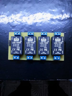
Hi Gep: that PCB with the LDDs looks terrific. Would you please explain the connectors on top, bottom and side?
I printed an Eagle scheme on a copper clad pcb, I developed with Hydrochloric Acid and H2O2, it's very easy... and my first time!
")
The connectors are linked to the Vin (top), Vout (bottom) and Arduino PWM signal (side).
OK Gep, that's what I guessed, but wanted to make sure.
Grazie!
You're welcome! And sorry for my very bad English! :facepalm:
Similar threads
- Replies
- 3
- Views
- 2K
- Replies
- 46
- Views
- 13K