bhazard451
New member
6 drivers doesn't seem very symmetrical... how about 4 H drivers per board? I would just use 2 boards on my build.
6 drivers doesn't seem very symmetrical... how about 4 H drivers per board? I would just use 2 boards on my build.
rrasco: that would be great if you would share your gerber files. I like these drivers much better than all the CAT's I built.
I'll work on getting the gerber files setup somewhere accessible.
I think I am still partial to my CAT drivers. These have less parts. The only issue with the CATs are that they are not always available.
RRASCO- Where did you get the EAGLE library for the MeanWell LDD's? I'd like to design my own PCB.
Thanks.
whats the difference between the CAT and the LDD-H? If you send me the gerber files, I can host them on another site(that I have admin rights on)
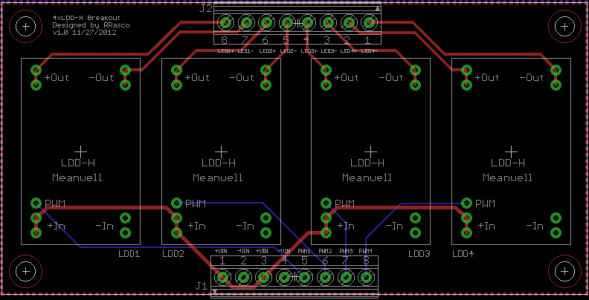
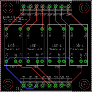
Two boards are now RTM. 5x5 LDD-Dx4 and 10x5 LDD-Hx4.
I will say, these are not tested. They are simple circuits that *should* work. Please use at your own risk. Having said that, I'm confident they will work.
You can obtain the files below. BRD and SCH files are also available in case you want to load them into eagle yourself. I strongly encourage you to do so; you might learn something. It also wouldn't be a bad idea for someone to double check my work.
The gerber files are contained in the zip and ready to be sent to itead.
http://code.google.com/p/meanwell-ldd-led-driver/downloads/list
I do beef them up, the supply traces are 24 mil. Wouldn't hurt to make them bigger I suppose, but I think this would be fine.
I like the dual board idea, except I would prefer not to cut anything if I'm having it manufactured. That's just me though.
I forgot to post these earlier. I had also updated the boards to use copper pours to clean up some of the traces too. I see you added copper pours to yours as well, O2.

Nice work Rrasco! I'll have to get my hands on some of these LDD drivers and give them a try. It's to bad that they come with fixed current values though, as I'm used to working with LM3409 based drivers that feature both analog and PWM dimming. I guess that there's always a trade off to be made, as these LDD's are certainly easier to build a pcb around LOL./4upLM340948voltv1.png[/IMG]
What size traces did you use for your LDD boards? I am trying to find some documentation on current limitations for traces. The LDD should never exceed 4A on a single board (@1A/ea), but if they are daisy chained together, it can jump real quick.
")