You are using an out of date browser. It may not display this or other websites correctly.
You should upgrade or use an alternative browser.
You should upgrade or use an alternative browser.
Minimalistic multichip DIY LED build
- Thread starter maglofster
- Start date
Lassef
Member
Quick question for those with multichips: Is it possible to clip the leads on either side so that you can power each row of leds separately? Clip it so that each row has it's own leads.
Nope, in a normal multi chip every individual row is connected together under the plastic covering
With the Dream Chip, Lumina 5.1 and some others, these internal connections are broken up and you can run 5 channels separately from each other.
@ 007Bond
Hey Lasse, are your drivers capable of pushing your DC above 150W if you want to? is the 200 to 400 par your desired target at the sand bed. Last question, what is the amperage you run to each of the 5 channels?---Rick
Yes, but due to the internal construction of the the driver board, I am for practical reasons, limited to about 200 to 210 W maximum effect inserted.
My target its minium 200 at the sand bed
With help of software I can adjust the current to each channel between 0 and 1400 mA. Just now I run the channels between 700 and 1200 mA. It is depending of the FV at each channel
Sincerely Lasse
TropTrea
New member
Are you using the 5 channel 100 watt multichip
Actualy I used the multi chip build only once on a taller tank. It was a 36" L 30" W and 36" tall custom tank that was 168 Gallons. May goal on that tank was 420 Watts of LED lighting with 6 lighting point sources of 70 Watts each.
Do to my sources I was able to get custom Stars where I built my own multi chips. Each Chip ran 6 Neutral Whites, 6 Blue, 12 Royal Blue and 6 near UV Chips each rated at 3 Watts each for a max capability of 90 Watts but I found running them in the in the 40% to 60% range of power gave the best results.
Unless technoology changes I would NOT do this build again because of available comercial chips and total cost. I ened up using 6 chips at roughly $80 each, Had another $40 into cooling each, plus 8 drivers at about $50 each for a total of over $1,000. Not a bargain by any means.
Add to this the time I spent on each of these arrays was roughly 100 hours working on this build. I think the build could have been improved if I would have been able to find some deceint lenses for these however with the arays being roughly 1 1/2" X 1 1/4" I was not able to find anything available for lenses.
The overall color was great with the individual drivers tuned in to the customers personal color taste. The way they ren finaly yeilded PAR readings of between 230 and 270 across the bottom and near the surface points where it exceeded 1,000 PAR.
It was not the neatest looking system but because the hood or canopy I made was 14" high over the tank it did look acceptable with everything hidden. The actual LED's were about 6" above the surface.
If I were to do it again what I would do a few things differently. First off find a comercial chip as this was my biggest pain. The Chip would have to be at least 15 Watts of near UV, 30 Watts of Royal Blue, 15 Watts of Blue and 15 Watts of Neutral White, for a total of at least 75 Watts. I would want a chip that readily had 60 degree or 90 degree Lenses available for them. I would want the add a controler so I could preprogram rather have pots adjusting power on the individual channels. And last I would completly redo the cooling which was in my mind the biggest goof on this build.
For tanks of 24" tall or less I personaly would not even consider a multichip build. The builds I did with indivdaul chips were only a fraction of this cost per Watt and the lghting was much more evenly distributed. Today with more 10 Watts chips being available I am leamning to indiviudual chips even more.
DrawnToBeaches
New member
Why do you use watts as a required parameter? Just out of curiosity, not all LEDs are created equal as far as their output/watt. Also single emitter setups aren't cheaper 
Lassef
Member
Why do you use watts as a required parameter? Just out of curiosity, not all LEDs are created equal as far as their output/watt. Also single emitter setups aren't cheaper
Lasse said:Yes, but due to the internal construction of the the driver board, I am for practical reasons, limited to about 200 to 210 W maximum effect inserted.
My target its minium 200 at the sand bed
Poor language. I use W as a measurement of my input - it gives some information about current an FV - but your right - it does not say anything about the quality of the light thats coming out from the LED
The second line "my target its minimum 200 at the sand bed" can be misunderstood. It should be " my target is minimum a PAR reading of 200 at the sand bed"
Sincerely Lasse
Lassef
Member
I adjust each channels amperage in order to have the same FV in all channels that use the same power source to their drivers.I was curious as to what amperage you run each color.
An average amperage of 900 mA gives around 150 W as consumption.
Normally I have a lower amperage in the actinic channel, but it is not always that way.
Sincerely Lasse
DrawnToBeaches
New member
TropTrea
New member
Why do you use watts as a required parameter? Just out of curiosity, not all LEDs are created equal as far as their output/watt. Also single emitter setups aren't cheaper
I find the Watts as a good rough guide as to how much total light is used considering I'm using LED's that are emitting light in the range of 90 to 110 lums per watt. The newer LED's out there are hitting the 140 lums per watt range range and using LED's with that much light output would require less watts per gallon as well. But you also need to balance the spectrum which is realy key. It is very easy to have a tank with a par of 400 and not have enough light for corals to grow compared to one with 250 Par of the correct light. This is why we balance the spectrum to be heavy on the blue or shorter wave lenghts.
As far as cost of build between the nigle and multi emiter is concerned that is realy dependent on the tank. The muti emiter set up I did costed over $1,000 plus at least 120 hours of my time. Considering it was a tank that was 36" tall I would say they results were much better using the multi emitters compared to single emiters but it had a lot of issues. For one I built my own multi emiters that was very time consuming and did not have any lenses available for them.
Where the cost goes up with single emiters is when the number of emiters required starts going up in count, and the available space above the tank increases there density.
General speaking using the older 3 watt emitters with a 4" spread between them is probably the least expensive build you can have. but for a tank that is 48" X 24" you are then limited to 72 emiters or roughly 216 Watts. Since we do not want run these chips at max it drops us down closer to about 180 watts. For a tank that is 24 tall that means your running about 1.5 Watts per gallon which will limit your coral selection on the substrate level. Going beyound this starts requiring more than passave cooling. But for a tank of 18" tall or less this is ideal.
Fortunatly today we have LED's out their running at 10 Watts on single emiters, and all the colors are available in the 5 watt emiters. You need a little extra space between the emiters for cooling but it is possible to to run over 48 5 watt chips to give you 240 watts to work with. Then the fact that these LED's are putting out 10% more light per watt than the older 3 watt chips you end up with a less expensive build and more light.
Now when your talking about a Tank that is 36" tall like the one I built the multi chip lights for it is a completly different story. The tank was 36" long, 30" deep, and 36" tall. a total of 168 gallons that I wanted to put around 400 watts of LED lighting on. Putting 400 watts of single emitter LED's into an area of 36" X 24" would mean roughly around 2 square inches of space per LED. So it was much more cost effective to build 6 seperate light sources with milti emiter's sharing a cooling system.
Fortunatly I had the resources to build my own multi emiters. But even at that if I valued my time at $1.00 per hour I would have been cheaper off buying comercial multi chips.
Keep in mind that the quality LED manufacturers only manufacture the Emitters themselves. The Stars we purchased are from a third vendor who mounts the emiters on the stars. They usualy mount one three or nine of these emiters on a single star and sell them to the retailers. It is possible to mount way more than this on a properly constructed system. But the more of these emiters mounted close together like this the more a heat issue that exists. Very often when you wee arrays of 36 emiters they are using 3 watt chips but do not recommend you run them at 100watts but at a much lower wattage to allow the heat to dispensate.
Do to my sources I was able to get custom Stars where I built my own multi chips. Each Chip ran 6 Neutral Whites, 6 Blue, 12 Royal Blue and 6 near UV Chips each rated at 3 Watts each for a max capability of 90 Watts but I found running them in the in the 40% to 60% range of power gave the best results.
.
where were you able to get 30chip custum stars made at only 80 bucks each???
I adjust each channels amperage in order to have the same FV in all channels that use the same power source to their drivers.
An average amperage of 900 mA gives around 150 W as consumption.
Normally I have a lower amperage in the actinic channel, but it is not always that way.
Sincerely Lasse
you might already be familiar with them but if you use meanwell LDD drivers or Sure Electronics (sometimes cheaper but similar design pcb only) you don't have to match input voltage from the PSU the driver does it for you by converting input voltate over the required output voltage into output current. They never run hot.
DrawnToBeaches
New member
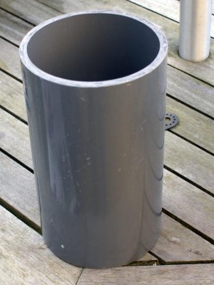
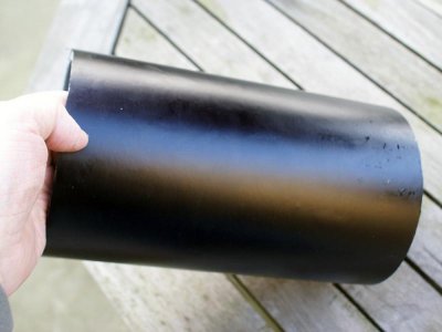
Lasse I really would like to know what you used for the casing and how you mounted your led in it. I've seen so many fixtures of yours and they've all been awe inspiring
TropTrea
New member
you might already be familiar with them but if you use meanwell LDD drivers or Sure Electronics (sometimes cheaper but similar design pcb only) you don't have to match input voltage from the PSU the driver does it for you by converting input voltate over the required output voltage into output current. They never run hot.
The only problem with LDD drivers is that they require an additional power supply from your AC to 48 Volts DC. Good quality DC power supplies are not inexpensive so you end up with another cost factor.
Some more
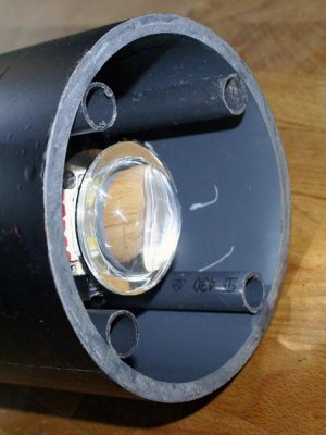
The lens
View attachment 236431
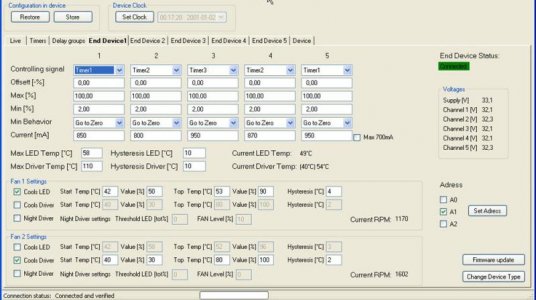
The configuration program
View attachment 236432
@ 007Bond. Look at the current fields to see my actual amperage. Channel 1: White 10 000K , channel 2: 455 nm, channel 3: actinic (420 and 430 nm), channel 4: 445 nm and channel 5: white 16 000 K
Sincerely Lasse
I see Lasse, thats what I wanted to know. What you were running your different colors at. Looks like you have them all about the same as far as power goes. I thought you were pushing your blues above the other colors. Are you just compensating with longer and shorter light periods for different colors?---Rick
you might already be familiar with them but if you use meanwell LDD drivers or Sure Electronics (sometimes cheaper but similar design pcb only) you don't have to match input voltage from the PSU the driver does it for you by converting input voltate over the required output voltage into output current. They never run hot.
Agree,I think the LDD's are a good solution for running these multichips. Way back in the thread there was concern that if you would lose a channel, the other channels would go to a higher voltage, then the talk went to mirror circuits as a safe guard. One LDD to each channel is a better solution, and like you said they adjust the voltage for you. :lmao:
TropTrea
New member
where were you able to get 30chip custom stars made at only 80 bucks each???
I doubt it if I will ever do it again. But I was able to get the "star" or boards through the company I was working for at the time and the emiters seperatly thanks to the fact they did large orders from these manufacturers for there product lines. What was not fun was trying to hand solder all these LED's under a 30X magnification system. The mountings were realy designed for automated flow soldering which I did not have the capabilities for.
I call them stars as most chips are mounted on stars but the pads were actualy square just under 4 square inches total area. I was reaserhing a completly different product and going through catalogs when I found these boards. They were listed as LED emitter mounts. They were offered in single, 3 up, 9 up, 16 up, 35 up, and 36 up. Since we were already ordering from this company I had a dozen of these added for my use. I was lucky I ordered a dozen as the first three I destroyed with my sloppy soldering skills.
I would not even attempt this without access to a profesional solder station. The soldering took me roughly 3 long weekends alone on these boards.
If my memory serves me correct I paid roughly $4.00 per board plus a couple cents over $2.00 average per emiter. The price per emiter varied as I got a good price break ordering over 200 of the Royal Blues.
Lassef
Member
you might already be familiar with them but if you use meanwell LDD drivers or Sure Electronics (sometimes cheaper but similar design pcb only) you don't have to match input voltage from the PSU the driver does it for you by converting input voltate over the required output voltage into output current. They never run hot.
This is a similar solution as the LDD (but its not mine solution - I only use it
The advantages is that you can adjust the current through software (and all the way up to 1400 mA) and it can be dimmed really low
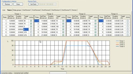
@007Bond You are right - I adjust the intensity of each colour through the timers/dimmers. And there is another possibility. If you look at the configuration program in my earlier post - you can find the row Max [%]. If I put let us say 80 % in one channel (or other % at all channels) - I will only get an intensity corresponding to 80 % (or whatever I choose) of the current in last row.
If you look at the picture below - you will find the programming for my aquarium just now. Timer 1 is the white channels, timer 2 is the RB channels and timer 3 is the actinic channel. You can see that the white channels only goes up to 80 % at the moment
@DrawnToBeaches: I´ll post some pictures later on
Sincerely Lasse
Similar threads
- Replies
- 11
- Views
- 430

