ZenMastr1968
New member
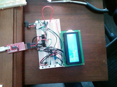
Mouser order arrived early.... Will start breadboarding and see how far I get.
pin 7 on DS1307 is a square wave output pin which is probably not connected because it is not needed or used.

2 Relay boards (4 relays each) on second MCP23008 controlled with only 4 wires from Hydra:
The boards above are the Futurlec opto relay 4 (10A @ 250VAC relays) - http://www.futurlec.com/Opto_Relay_4.shtml I don't think we'll be able to beat that at $14.90 per populated board (thanks for pointing these out earlier in the thread). It is nice that you can daisy chain 2 boards. There is also some proto area on them for the MCP23008. That way the relay box can have only 4 wires to it from the Hydra.
Yes it needs a 12V, and I'm using a separate PSU for the relays. I've been using a 9V for Hydra, but I'll be stepping down to 7.5V probably.
Try this
male headers select through hole and apply filter select pin headers and apply filters
or maybe this linkMale Headers
It still leaves a lot, but the 6th one down looks close.
NOTE: You do not have to by the exact size. Sometimes you can get a double row that is like 50 pins long and they just snap where needed. They might be cheaper.
Hope this helps
[EDIT]
50 pin version
")

Zen, you asked about software. terahz and I have basically been sharing via email. I suppose it's time to put some things up on the code site so we can share/get input from a wider audience.
This isn't really as organized or consistent as I'd like, but to get something started: In trunk>software I created "libraries" and "sketches" directories. In the libraries directory I put an LCD library from terahz, which is the one we're both using right now. Also put an etherShield library up, which is a library I found online for the ENC chip. I have this compiling against sample sketches but haven't actually tried to use it yet.
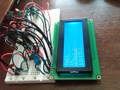
In the sketches directory I put "hydra_test" which is the sketch I was using when I made the post a few days ago of the LCD and RTC working. This sketch has code for those two functions, and should get you started.