Must-haves for EASY DIY controller?

The 1302 is the SPI version of the chip, right? Why'd we want to switch to that instead of the I2C 1307 (which we could also use a supercap for)?

I shyed away from the supercap mainly because I couldn't get any solid info on an implementation using that concept, but if you think we can work it out, I'm all for it. The part that I don't get is this: If you simply wire the supercap from GND to VBAT, how does it ever get a charge?

That said, I just bought a 10-pack of those batteries so I should be good for a while. :D

THe 1307 can't charge the supercap. What you're describing is exactly how it works on the 1302. No special addition are required. The IC has trickle charge circuit that takes care of the supercap.

I got new battery yesterday and measured it at 3.3V. We'll see how long that charge lasts now :) I think the reason people get the 23xx series batteries is because they have 3-4times the charge as the 12xx.

In any case, the battery shouldn't be a problem with the controller connected to a power source. I think I had mine unplugged for a few weeks, that's why it drained the battery that much. I just never expected it to die that quickly :)
 
My pH amp is misbehaving. It's not responding consistently and won't calibrate. I'm betting my probe is dead but in the meantime am wondering something about the circuit - do we need to invert Vin and then regulate it to -5v, or can we just invert +5v? Doing so would lose a few parts AND would let the whole board run on USB power or another regulated 5v source.
 
My pH amp is misbehaving. It's not responding consistently and won't calibrate. I'm betting my probe is dead but in the meantime am wondering something about the circuit - do we need to invert Vin and then regulate it to -5v, or can we just invert +5v? Doing so would lose a few parts AND would let the whole board run on USB power or another regulated 5v source.

Inverting +5V... It might work. The ICL7660 is rated at 99.9% efficiency and one of its features is "input 5V to get +/-5V"... might be worth a try.

However USB will not have enough current to drive the Hydra. Mine, when fully populated and connected to relays, goes in the 700-800mA area.

I have a spare PH probe laying around, I can mail it to you if you are interested.
 
Well even if the whole thing won't run on USB, it would relax the requirements a bit and let us lose that other reg. Plus, if it worked, people could make the pH circuit "standalone" as you initially did, and just feed it 5v instead of having to feed it a higher voltage.

Thanks for the offer, I'll send you a PM if I want to take you up on it. I'm wondering if I might have hosed the circuit somehow though because even with a completely dead probe, I'd guess that tweaking the calibration trimpots would result in SOME sort of change to the output, but on mine, the trimpots do nothing when the probe is connected (and without the probe, it's floating, so pretty meaningless). I may breadboard just the pH circuit or solder up just that portion on another Hydra PCB to play with the "invert 5v" option anyways.
 
Does anyone have a set of compleat plans for this DIY controler? Pictures, schematic's, programing, where they bought the stuff? If so please PM me with them. Ive been dieing to build my own controler, but this post is all over the place, and would take hours to decpher. Thank you in advance.
 
DeepSeaBeauti, see the posts by nauticac4 near the top of this thread - it's all over because we're still figuring things out. :) There isn't yet a 100% final guaranteed to work end product.

That said, if you do want to build one, please do! You can give us feedback that helps revise the design as we complete it. The design is stored on a google code site:

http://code.google.com/p/hydra-reef/source/browse/

Click on trunk, then hardware, then hydra in the file tree on the left. The right pane will have the Eagle brd and sch files, and a spreadsheet listing the bill of materials and sources for most parts. If you need help interpreting this information let us know.

Or, you can wait a few months until we have things more sorted, at which point we'll post another thread that will act as a simple how-to guide for building and using the final product.
 
Check out the google code site I just posted - it has the schematic for the whole board. The pH circuit is a bit buried but it should be clear when looking at the schematic since it's the only circuit using op amps.

If you want the pH amp that this design is based on, you could ask terahz, as he is where I got it from originally.
 
Just very quickly (I am at work lol) to explain my controller (maybe that can give you some ideas ... )
I do use one PIC on my controller. The display is a big graphic LCD with touch screen. I am using a RTC on I2C and Expander on I2C also. The ethernet connection is on SPI. The I2C is software one because the issue with the SPI.

For the software, I use MIKORC PRO .... Pretty good stuff.

I can say that 90% of the hardware is done ... need the PH electronic now.

For the software, I have only the Ethernet part left to do (No idea how to do that lol need big help for that specially html code)

My controller will not be programmable ... everything will be set up. He's controlling Time, date, chiller, fan, top off, led, sunrise, sunset, moonlight, MH, T5 and advance wavemaker
 
All I can think of at this point is to move all "legs" in the corners or at least the one that is next to the main AVR on the other side of FTDI1 and FTDI2.

Done.

Also, if possible, leave enough space around the main vreg for a small heatsink. Just because running the relays, few pwms + reference for LEDs, 2 avrs, ethernet etc. adds up and heats up the reg a bit.

If it works out to remove the negative voltage regulator, we'll have more room down in that crowded corner and I'll do a more thermally efficient design.
 
terahz or others, what do you think about switching to an LDO regulator instead of the standard-issue 7805? Would mean we could use a lower voltage wall wart, dissipate less heat, and maybe get away with not needing a bigger package and heatsink.
 
DeepSeaBeauti, see the posts by nauticac4 near the top of this thread - it's all over because we're still figuring things out. :) There isn't yet a 100% final guaranteed to work end product.

That said, if you do want to build one, please do! You can give us feedback that helps revise the design as we complete it. The design is stored on a google code site:

http://code.google.com/p/hydra-reef/source/browse/

Click on trunk, then hardware, then hydra in the file tree on the left. The right pane will have the Eagle brd and sch files, and a spreadsheet listing the bill of materials and sources for most parts. If you need help interpreting this information let us know.

Or, you can wait a few months until we have things more sorted, at which point we'll post another thread that will act as a simple how-to guide for building and using the final product.


Ahh this is good stuff!! Ok great, i work as a pricipal Technician at bnl here on LI, i build electronics all day. Im gonna sit down with one of the engineers and try to work something, and purhaps give everyone my 2 cents. Maybe even show off the plans we have been working on for a vortech style wave maker. :D
 
a buck difference at worst. A few of the caps might (or might not) need different values depending on which reg we went with and we might need a different package, but really it shouldn't be a large impact.

The one caveat is that doing this is only beneficial if people use a lower-voltage supply. As the board is right now, you could probably get away with a 7.5v wall wart and have less heat than we're seeing (I think terahz and I are both using 9v wall warts) so maybe that would be enough. If we go to a very low drop out regulator and use a better reverse polarity scheme, we might be able to get by with a 6v wall wart. But are those common enough, and is the problem large enough, that it makes it worthwhile?
 
Although neither you or I plan to use them,I thnk the ELN folk need to be considered I may not understand this completely, but wouldn't they then need a second 10 volt supply for the PWM of the ELN? It would be nice if they don't ned a second supply.

Although from my point of view this sounds fine, but I think we want to design for the masses.
 
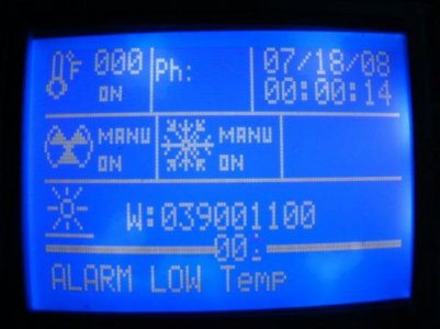
here a ugly picture (Promise the LCD is FLAT lol) of my main screen of my controller

attachment.php
 

Attachments

  • DSC04216.jpg
    DSC04216.jpg
    30.8 KB · Views: 8
FishMan, you're correct, and I think you're right about designing for the masses. Using an LDO reg would make no sense if people were slapping higher-voltage wall warts on it anyways.

OTCHU, that looks beautiful. I'd love to use a big screen like that on a Hydra. Maybe in version two we can plan for it.

My consensus about the Hydra mainboard. Right now it seems like we're facing two problems:

1) We're worried about memory on the main AVR and haven't even implemented Ethernet yet
2) The Ethernet hardware doesn't seem to be working in the current design anyways. Even with the two fixes I mentioned earlier, I still get zero response. I watched the various SPI lines as the device booted and it does look like the Arduino is trying to talk to the ENC chip, but it never does anything. Could be a hardware or software problem, but I don't know where to troubleshoot either way.

At this point, I'm wondering if we might be best served to remove the Ethernet circuit? People who want it can get an ENC-based shield for ~$20, or an "official" Arduino Ethernet shield (Wiznet based, which needs less program memory space anyways) for maybe ~$30 - $40. This would free us from the resource problems, give us board space, and we wouldn't have to troubleshoot the non-functional hardware. It would also remove most of the SMT components and would probably help us convince people that we stayed true to our roots of keeping this an "easy" project.

With the increased board space, we could easily design a more robust power section that could handle all our needs, i.e. we'd have room for a heatsink on the 5v regulator and/or whatever other measures we needed. We'd also have plenty of room to break out a one wire header, and a header for the IR receiver, etc.

Or, we could troubleshoot the hardware, and continue on the current path. Leaving the Ethernet embedded might save folks who want it $10 - $20 vs. buying a shield, so I guess we have to decide how valuable the advantages of removing it are.

Thoughts?
 
I think this makes $0.04 now. Lost count of how many pennies of thought I have added.

IIRC the Atmega328 has slight issue with the pin out compatibility. If so how much do we care? Do we expect to stack a lot of Arduino shields on this? If we keep Ethernet I doubt it - they will probably be custom. And if not wouldn't a few pin changes to the code solve the problem?

So I think switch to the 328 (more code space) get rid of the second Arduino (more board space, more board space?), no processor to processor comms (more code space, easier debug)). Will changing to the 328 give us enough board space for the power requirements.

[EDIT]
I realize we are staying away from surface mount, but just a thought. The TQFP 32 package for the 328 has the pin spacing at about 1/32 of an inch. With a fine tipped soldering iron I think this is doable for most people. Even more board space. $0.06

DWZM, you seem to be against the 328 m- or maybe it just seems that way. Can you list the problems/issues again.
 
Last edited:
FishMan, I think you're confused, or maybe I am - we're already using the 328 which has 32kb of progmem. This is the standard Arduino chip right now (the 168 and 8 came before it). Above, we were debating switching to the 1280, which has 64kb of progmem, more I/O, and different (but compatible) pinouts for some of the standard hardware features. The 1280 is only available in SMT. I also mentioned the 644, which is used in the Sanguino - it has more progmem, a few more I/O, and is available in a HUGE through-hole package.

The issue with an SMT chip, besides soldering, is that people would need to burn the bootloader to it. Probably not an issue for folks like you, me, terahz, etc. but IMHO it conflicts with the goal of this project.

I really don't think the proc-proc communication will be an issue once we nail down what functions each processor will be doing. There are a bunch of well-proven (but simple) examples of I2C for "arduino to arduino" communication.
 
Back
Top