Must-haves for EASY DIY controller?

I have a quick question. I have been reading through and looking at the schematic under eagle.
How does the LCD backlight get power? I see it labeled BKL+ on the LCD, but doesn't seem to have anywhere else on the schematic labeled the same to supply power.
Thanks
 
Irecieved my parts the other day. Part #517-850-01-19, X3 is this the right header should it not be #517-850-01-18 or am I looking at this wrong
 
It doesn't really matter if you have 18 or 19, you can cut them.

For future reference, it's a lot cheaper to buy the 40 pin strips from moderndevice, etc... instead of ordering these from mouser like this.
 
Relay boards!

HPIM1296.jpg


HPIM1298.jpg
 
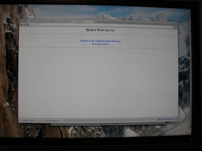
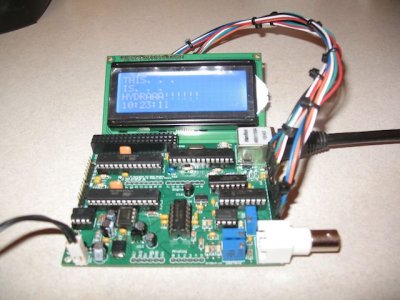
Up and running

Up and running

Thanks TeraHz, DustinB, and DWZM, and the many others that have contributed to this forum.
 

Attachments

  • IMG_3193.jpg
    IMG_3193.jpg
    33.5 KB · Views: 6
  • IMG_3195.jpg
    IMG_3195.jpg
    58.1 KB · Views: 6
Those relay boards turned out nice. I really need to order some, been insanely busy lately though.

nauticac4: If you are wanting to make the BOM, you might make a note on the transistors. Use a NPN for normally open or a PNP for normally closed. I haven't done any testing, but this is what I had in mind for the solution of possibly turning the pumps off if a software/hardware glitch happened. Still not entirely sure how effective it will really be.
 
In addition to the BOM for the relay boards, could we get a Gerber zip file to have the boards made. If anyone want to split an order of boards PM me.
 
Ill try to knock it out on my lunch break today. I feel the boards need to be tested to make sure everything is correct before putting gerbers up. DWZM has the final say on what goes onto the code site so its not my call. Trying to get up with LiveRockMAster to get a few of his boards for testing.
 
Has anyone put their Hydra in an enclosure yet?

I put mine on an enclosure - I was going to put it inside (black plastic project box), but then I realized I like playing with it so I need access to the headers. So I took off the top of the box, turned it upside down, and mounted it on top. Then I drilled holes to mount the LCD panel on the side. This gives me a 'finished' look good enough for me, and still have access to the headers for playing. I am in the process of putting together a build thread, I will have photos in there.
 
pH Circuit Problems

pH Circuit Problems

I am using a 12V power supply and the pH circuit doesn't seem to not be working in my setup.

A long way back there was an issue with 7660 having only an input range of 1.5 - 10V. The part number in the BOM for DigiKey ICL7660CPA-ND still shows this part as 1.5 - 10V.

Would DigiKey PN ICL7660ACPAZ-ND be a better part maybe? This part has a 1.5 - 12V input voltage range. I am going to order a couple of these if I cannot find a lower voltage wall wart laying around.

Can anyone tell what voltage they are getting on pin 5 of U10 from Pin 3 on U10?
Also Pin 3 on U10 to GND Pad on PCB board.
 
Speaking of enclosures, I had considered using one of those Sterlite shoebox sized boxes so the top could pop off conveniently. That should be easy enough to cut the holes for the LCD, power, power strip, ethernet, pH, etc.

BTW, can this thing be enclosed without a fan?
 
Think I got it figured out

Think I got it figured out

Pin 3 was not connected to ground on U10. I just ran a jumper wire to the ground plane on the PCB and seems to work much better now.
 
Does anyone have the BOM saved as a project on Mouser, that they could share with me directly, so I don't have to go about importing it. Send me a PM thanks!
 
Back
Top