My Neptune Apex web interface compatible DIY reef controller

I think there is a fault in your code.
When no sensors is available the loop contains running.

Code:
boolean initPH() {
#ifdef _PH  
  char phchars[15];
  phchars[0]=0;
  Serial1.begin(38400);
  for (int i=0;i<255,strlen(phchars)==0;i++) {
    Serial1.print("e\rr\r");
    delay(384);
    getresponse(phchars);
  }
This line
Code:
 for (int i=0;i<255,strlen(phchars)==0;i++) {
has to be this line
Code:
for (int i=0;i<255;i++) {

if you don't have any ph sensors, then you would comment out #define _PH, so the block of code won't even be included.
If it was disconnected, condition strlen(phchars)==0 will always be true, and i will eventually get to 255. The two conditions are ANDed.
(you can specify multiple conditions in a for loop).
 
Last edited:
Doughboy I have a problem. See code below, 192.168.1.66 is the PC i use to load the arduino but it wasn't connected by usb when this report ran.

05/11/2014 13:55:52 192.168.1.66 /cgi-bin/status.json
05/11/2014 13:55:56 192.168.1.66 /cgi-bin/datalog.xml?sdate=1405101308&days=31
05/11/2014 13:56:25 Get ntp failed.
05/11/2014 13:56:25 Using RTC as sync provider.
05/11/2014 13:56:25 RTC time 05/11/2014 13:56:25
05/11/2014 13:56:26 System initializing...
05/11/2014 13:56:28 Network initialized.
05/11/2014 13:56:30 Temp sensor initialized.
05/11/2014 13:56:31 Outlet Timers initialized
05/11/2014 13:56:35 Initialization Completed.
05/11/2014 13:56:35 3587


you can test running just the ntp test sketch on your mega+ethernet shield. just google arduino ntp sample sketch.
you can try a different ntp server.
do a ping pool.ntp.org and see what the ip address it uses, then use that instead of the one I used in config.h. For example, I just pinged it now and I got 130.60.204.10, so change the #define to

#define NTPSERVER 130,60,204,10
 
I tried the example quickly and got an error. What Ethernet shield are you using? Mine looks different and that might contribute to it.
 
2014-05-12-09-00-27.png


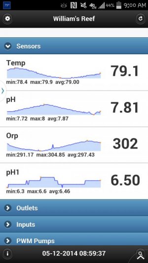
Here's a screenshot of the controller with Temp, 2 pH and Orp
 
wgraham said:
The only problem I have so far is that the Orp will give a hi reading once in a while up to 3200. Also if I change the pH1 to Ca RX the graph will go away.


Try changing in apex.ino your FLASH_STRING apex_ph11 name to Ca RX and apex_ph12 type to pH.
 
About the Orp is there anything in the sensors.ino that I need to change to make the Orp not to jump to hi numbers. Other than that its working fine. It doesn't show on the graph unless it happen at the 10 min interval. But my email notification sends out an email every time it happens. So I no that the email is working correctly
 
ok, you have to match the value of probe name to the name used in sensor log.

try changing (backup first) that to Ca_RX, and the probe name Ca_RX. (you'll have to wait for sensor log data to accumulate again before you get graph data).
the probe type should be ph, not ph1.
probe name can be anything (I think no spaces).

I think this line also
FLASH_STRING(apex_json5b,"},{\"did\":\"base_pH1\",\"t\":\"pH1\",\"n\":\"pH1\",\"v\":");

should be
FLASH_STRING(apex_json5b,"},{\"did\":\"base_pH1\",\"t\":\"pH\",\"n\":\"Ca_RX\",\"v\":");

I change the code to what you posted and the graph still left, replace it with pH and it came back. What do you mean change backup first
 
here's my feeble attempt at containing this beast :)

my RTC still needs to be fastened down, still need the reset switch mounted in the front plate, and still need a back plate made but I think it's gonna work fine....

I'll add a DB9 connector to the rear plate so I can use the relay set-up I made for my Ferduino controller on either controller (my plan all along :) )

IMG_3208_zps0f5c891d.jpg


IMG_3209_zps1aabc80d.jpg


IMG_3210_zpsf3b2c666.jpg


notice the red proto extension to the ether shield? I wanted to " level " it all out there, I'll use that for most of my connector wiring but if it's not enough, I still have room for 1 more proto board on top of the stack

IMG_3211_zps23a243eb.jpg


IMG_3215_zpsb5ab3c86.jpg


as you can see, still room for 1 more proto board on top and room to the left for the pH circuitry, but it's tight in there LOL

IMG_3216_zps28da28db.jpg


I have to make a back plate that hopefully will contain all the needed connectors to make everything else work properly :)

this was an old RCA TV channel selector box, since I only use HDMI HI-DEF now for my TV equipment, this box was no longer needed for it's original purpose :)
 
Nice work red top. I've been using the hacksaw recently too but getting discouraged by the programming. I can't get even the basic examples to fetch NTC time. I'll post my project box soon.
 
Nice work red top. I've been using the hacksaw recently too but getting discouraged by the programming. I can't get even the basic examples to fetch NTC time. I'll post my project box soon.

Try the chauvet16 without modifying anything but the ip address and see what you come up with. Make sure you have temp and ph sensors connected.
 
Back
Top