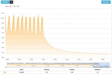
The ORP was cycling, very consistently, at roughly-215 to 0 mV, as you can see from the graph. If the filter is producing hydrogen sulfide because the ORP or flow is too low (not sure I buy that it was hydrogen sulfide) then why should I lower either of them further? Lowering carbon, I can see but it is going to limit my ability to control the ORP cycle, I believe.
If the favorable to less favorable electron exchange goes(redox cascade):
Oxygen, Nitrate then, if any organic material is left to break down, Iron then Sulfate. I don't see how we ever get to sulfate, unless there is very little iron. I'm not saying it can't happen, just that it would seem unlikely and there are a lot of things that can produce a stinky smell. What is in skimmate? That smells about the same or my armpits, when I sweat.
All we are measuring is ORP, while driving the ORP over a 500 mV range, down from ~+300 to ~-200mV range. This means the material in the chamber is going from an oxidizer to a reducer, at least from a measurement standpoint (from needing electrons to being able to provide electrons), yet by the time the water exits that chamber and reaches the second ORP probe in the buffer (third) chamber, the ORP has already shifted positive again. Where did that exchange potential go and how is ORP an indication of the reaction we are trying to drive? Unfortunately, I don't really understand how the ORP relates to the reaction, I am just trying to duplicate the readings suggested in the manual. My assumption is that the ORP is an indication of the status of that favorable to less favorable electron exchange.
I thought the idea was to allow the fine sand bed to reduce ammonia to nitrite then nitrate, through normal aerobic nitrification processes. Then, have that feed into another layer (or chamber in my case) where heterotrophic bacteria is produced, by dosing carbon. Since there is minimal oxygen in that layer or compartment, the bacteria bloom, starts to work it's way down the redox cascade, breaking down the nitrate. Once this occurs, the excess bacteria and nitrogen gas are flushed out into the main tank where the bacteria can be consumed by corals and pods and the N2 gassed off?
Sorry. It may seem like I am trying to argue here but I am really just trying to run through the logic and see if I am understanding things correctly.
I think I have talked myself into replacing the media with something more course to allow better flow when it's time to restart the cycle.
")