saltyclaus
New member
Hi,
Allow me a brief introduction:
In 2013 we decided to get into the marine aquarium hobby. Due to renovations (sounds familiar dartier?) and professional changes we paused the implementation of the planned system just after the tanks were delivered. After reading through this thread, seeing the first test setups and others in the making, I decided it was time to (re)register with RC and chime in.
Afterall, the system we are creating was planned as a traditional Berlin with a twist: an emphasys on heavy feeding and additional nutrient export with an ATS, wet skimming water change and carbon dosing. During the long pause the dymico system came to my attention when the hobby beta was announced. I have been following it ever since with the idea to create a diy version some day as additional or even as replacement for export but also as an alternative to a proportional pricey CR.
My attempt at a dymico won't be around soon. I have to finally get the system up and get some fish and invertebrates in the house :lolspin: There is a lot of remaining work before that'll happen. Hence, the dymico will be integrated later in the running system, probably as soon as water changes can't keep up with Ca demand. In the meanwhile I'ld like to offer my insights in the dymico system so far as well as any translations if new info pops up (I'm Flemish = Dutch native speaker). Lastly, I am a .Net architect professionally (big word synonym for nerdy programmer) so could assist with the programming logic and flow. I envision a pseudo-program that is readable by many and can be translated in whatever needed language (python, Arduino C, C#, reef angel, ...).
As a first contribution I'ld like to share the following (which you all probably have seen but I haven't seen it in the thread). It's a post by Tim Wijgerde (phd involved with the research behind dymico) on a dutch forum in which an (english) excerpt from the facebook page was posted:
Quoted from: http://www.zeewaterforum.info/forums/archive/index.php/t-147132-p-3.html
I believe most of the info is still accurate (it predates the release of the hobby systems) except for the average mV of -200. The manual V13 mentions an operation range between -250/+250mV with going into alarm at -300/+300mV so the average is probably closer to 0?
Another thing of note for me was that carbon is dosed once per hour. So, not the frequency changes, only the dose fluctuates depending on redox value. Together with the sinusoïdal pattern of the cycles this makes me think of the system as a perfect candidate for a machine learning algorithm. Considering the bio-load of a closed system is fairly constant, the swings in redox value combined with the nitrate knee moments allow for a self adjusting system: let the program alter the parameters dynamically to achieve the desired min/max redox and cycles/hour. That would introduce an evolutive system that adapts to any bio-load and filter capacity combination as long as the system can sustain the desired outcome.
Ok, guess I should stop the rambe here for a first post (too late right?). I look forward to seeing all your updates and will eagerly contribute where desired")
Allow me a brief introduction:
In 2013 we decided to get into the marine aquarium hobby. Due to renovations (sounds familiar dartier?) and professional changes we paused the implementation of the planned system just after the tanks were delivered. After reading through this thread, seeing the first test setups and others in the making, I decided it was time to (re)register with RC and chime in.
Afterall, the system we are creating was planned as a traditional Berlin with a twist: an emphasys on heavy feeding and additional nutrient export with an ATS, wet skimming water change and carbon dosing. During the long pause the dymico system came to my attention when the hobby beta was announced. I have been following it ever since with the idea to create a diy version some day as additional or even as replacement for export but also as an alternative to a proportional pricey CR.
My attempt at a dymico won't be around soon. I have to finally get the system up and get some fish and invertebrates in the house :lolspin: There is a lot of remaining work before that'll happen. Hence, the dymico will be integrated later in the running system, probably as soon as water changes can't keep up with Ca demand. In the meanwhile I'ld like to offer my insights in the dymico system so far as well as any translations if new info pops up (I'm Flemish = Dutch native speaker). Lastly, I am a .Net architect professionally (big word synonym for nerdy programmer) so could assist with the programming logic and flow. I envision a pseudo-program that is readable by many and can be translated in whatever needed language (python, Arduino C, C#, reef angel, ...).
As a first contribution I'ld like to share the following (which you all probably have seen but I haven't seen it in the thread). It's a post by Tim Wijgerde (phd involved with the research behind dymico) on a dutch forum in which an (english) excerpt from the facebook page was posted:
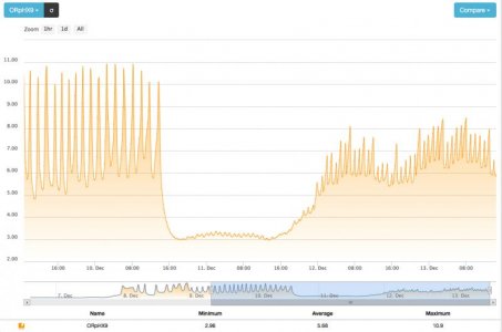
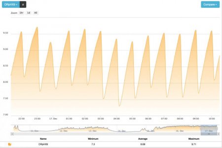
1. Seawater is actively drawn through the sand bed with a return pump. This means the system is not dependent on diffusion of nitrate and carbon into the sand bed. The amount of water filtered is controlled by the redox value measured inside the sand bed by an IKS Aquastar computer. The lower the redox value, the less oxygen is present in the sand bed, and the more water is filtered. The opposite is also true, where higher redox values trigger less pumping time. This results in a sinusoidal redox value, which fluctuates around an average value of about -200 mV. This value is ideal for denitrification.
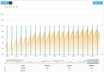
2. The sand bed receives a carbon source every hour, which the bacteria use to break down nitrate. This also ensures that carbon does not have to diffuse through the sand bed, like in conventional denitrification systems. Again, this process is controlled by the computer. The lower the redox value, the less carbon is injected. Higer redox values trigger more carbon injection into the sand bed, to stimulate oxygen consumption by bacteria.
3. The sand bed also receives carbon dioxide (CO2) injection, based on the requirements of the user. A pH of 7 is sufficient in most cases to result in high calcium, magnesium and KH/alkalinity levels. DyMiCo works as a powerful calcium reactor, with a capacity of about 10% of the total system volume.
4. Finally, the carbon source and CO2 are actively and horizontally pumped through the sand bed, to ensure that the sand bed is evenly affected. This prevents black patches of sulphate reducing bacteria that produce toxic hydrogen sulfide gas (H2S), a common problem with conventional sand beds.
5. Because the entire aquarium water volume is filtered only once per 24 hours (on average), it removes less plankton and feeds from the water. This is why DyMiCo aquaria are richer in plankton (algae, bacteria and crustaceans) and filter feeders such as sponges, when compared to Berlin systems. The system also uses very little energy, and requires no water changes or Balling additives (calcium chloride, magnesium chloride or sodium bicarbonate).
Quoted from: http://www.zeewaterforum.info/forums/archive/index.php/t-147132-p-3.html
I believe most of the info is still accurate (it predates the release of the hobby systems) except for the average mV of -200. The manual V13 mentions an operation range between -250/+250mV with going into alarm at -300/+300mV so the average is probably closer to 0?
Another thing of note for me was that carbon is dosed once per hour. So, not the frequency changes, only the dose fluctuates depending on redox value. Together with the sinusoïdal pattern of the cycles this makes me think of the system as a perfect candidate for a machine learning algorithm. Considering the bio-load of a closed system is fairly constant, the swings in redox value combined with the nitrate knee moments allow for a self adjusting system: let the program alter the parameters dynamically to achieve the desired min/max redox and cycles/hour. That would introduce an evolutive system that adapts to any bio-load and filter capacity combination as long as the system can sustain the desired outcome.
Ok, guess I should stop the rambe here for a first post (too late right?). I look forward to seeing all your updates and will eagerly contribute where desired