Tempp control Circuit
Tempp control Circuit
Here is the temp control circuit I have on my PLC, it is not my own design. There is another simple ckt for the pH probe, the moisture alarm (either sump or show overflows), water level, and various LED controlling circuits i can also post if anyone shows interest.
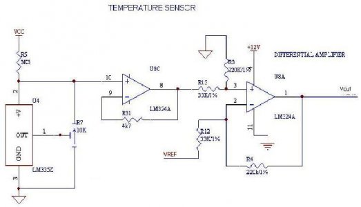
This circuit will switch the PLC off if the ambient temperature rises above a definable level, thus turning off the heater. It will also switch the PLC back on once it thinks the temperature has gone back to normal. The operating temperature range of this circuit is between 0 and 158 degF.
The temperature sensor is a National Semiconductor LM334Z IC. The device is potted and remains in the water. This device converts ambient temp around the IC to a particular voltage, with 10mV per degree Kelvin as its standard (R7 sets the output voltage of the device). In other words, at 0 degC the device will deliver about 2.73 volts. Put another way, 0 degK equals 273.15 degC, and 70degC equals 343.18 degK, soââ"šÂ¬Ã‚¦
Minimum Voltage = 273.15 *10E-3 = 2.73 volts
Maximum Voltage = 343.18 * 10E-3 = 3.43Volts
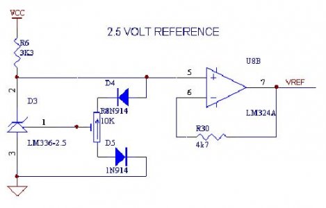
This voltage is amplified by LM324A (pin 8). It is then compared to the reference voltage of 2.5 volts from LM336-2.5 and amplified through a differential amplifier with a differential gain of 220/47 = 4.69. Looking at the diagram, pin3 is subtracted from pin 2 and amplified at the output at pin 1.
Boiled down, from an input voltage swing of 2.73V to 3.43V, there is an output voltage swing of 1.07V to 4.36V,
(2.73 ââ"šÂ¬Ã¢â‚¬Å“ 2.5) * 4.69 = 1.07V
(3.43 ââ"šÂ¬Ã¢â‚¬Å“ 2.5) * 4.69 = 4.36V
For my tank I have set the temp to 79 degF which equals 298.56 degK. Which equals 2.99 Volts
(2.99 ââ"šÂ¬Ã¢â‚¬Å“ 2.5) * 4.69 = 2.3Volts
When the PLC senses anything greater than 2.3 VDC it opens a normally close relay, which in turn opens the circuit that controls the line voltage to the heater. Below 79 degF the circuit is made and the heater is on.


