PC based Controller

barebottoms said:
What kind of system will this be? A stand alone? I'd like to see at least 2 ph probes. Another serial so we can put a IP stack on it and SLIP out the other port if its a stand alone, or an ethernet phy.

Basically it would be a serial converter. It would allow you to control and monitor the tank via a serial link. This way you could control it from linux, windows, palm etc. Since all you will need is the ability to send and receive serial. You could also use a serial to USB adapter, and connect it via usb.

2 ph probes would be easy enough to do. A second serial port would be fairly easy as well.
 
some questions:

pH probes-> what is the most popular one out there and what sort of probes should be supported. My guess is that most people use the cheapest one that does a fair job and has a reasonable life span.


temp sensor-> see pH probes. Where do you guys want to put these. I am assuming maybe one to measure the water temp but maybe somebody wants another one to control fans for the light setup.

Any thoughts
 
Chris,

I posted my wish list, and I am ready to shell out some $$$ and some time. What is next??

Maybe we should start a new thread, and list who is going to do what, and who is realy serious about going on further with this project.
 
Wireless Ethernet!

Wireless Ethernet!

I really think this controller would be great if we could get it interfaced to 802.11b wireless ethernet. Then your computer can be anywhere on your "home network". No running serial cables from your tank to computer or putting a PC under your tank.

This company is giving away a free version of embedded Linux:

http://www.snapgear.org

Haven't looked into it enough to know what processors it supports or if wireless ethernet could be added easily.

-- Leslie
 
Tempp control Circuit

Tempp control Circuit

Here is the temp control circuit I have on my PLC, it is not my own design. There is another simple ckt for the pH probe, the moisture alarm (either sump or show overflows), water level, and various LED controlling circuits i can also post if anyone shows interest.

This circuit will switch the PLC off if the ambient temperature rises above a definable level, thus turning off the heater. It will also switch the PLC back on once it thinks the temperature has gone back to normal. The operating temperature range of this circuit is between 0 and 158 degF.
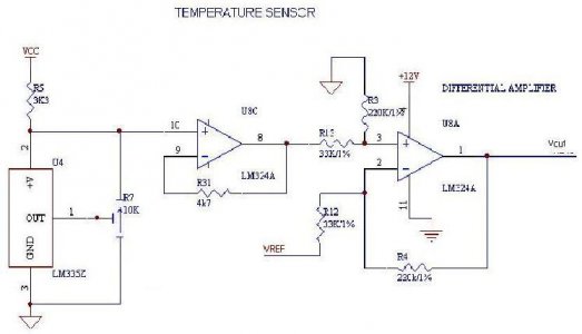
The temperature sensor is a National Semiconductor LM334Z IC. The device is potted and remains in the water. This device converts ambient temp around the IC to a particular voltage, with 10mV per degree Kelvin as its standard (R7 sets the output voltage of the device). In other words, at 0 degC the device will deliver about 2.73 volts. Put another way, 0 degK equals 273.15 degC, and 70degC equals 343.18 degK, soââ"šÂ¬Ã‚¦
Minimum Voltage = 273.15 *10E-3 = 2.73 volts
Maximum Voltage = 343.18 * 10E-3 = 3.43Volts
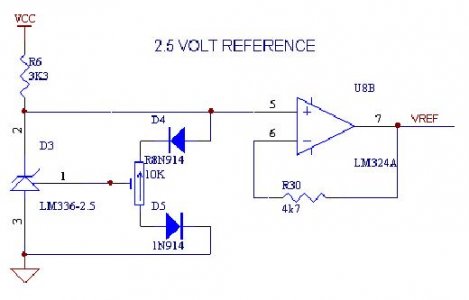
This voltage is amplified by LM324A (pin 8). It is then compared to the reference voltage of 2.5 volts from LM336-2.5 and amplified through a differential amplifier with a differential gain of 220/47 = 4.69. Looking at the diagram, pin3 is subtracted from pin 2 and amplified at the output at pin 1.

Boiled down, from an input voltage swing of 2.73V to 3.43V, there is an output voltage swing of 1.07V to 4.36V,
(2.73 ââ"šÂ¬Ã¢â‚¬Å“ 2.5) * 4.69 = 1.07V
(3.43 ââ"šÂ¬Ã¢â‚¬Å“ 2.5) * 4.69 = 4.36V
For my tank I have set the temp to 79 degF which equals 298.56 degK. Which equals 2.99 Volts
(2.99 ââ"šÂ¬Ã¢â‚¬Å“ 2.5) * 4.69 = 2.3Volts
When the PLC senses anything greater than 2.3 VDC it opens a normally close relay, which in turn opens the circuit that controls the line voltage to the heater. Below 79 degF the circuit is made and the heater is on.
 
Hi,

Since the controller would basically be just a serial interface, you could connect it to a laptop with a wireless card in it, or a pocket pc etc. As far as actually building ethernet into the controller, it could be done, but since the system is to be controlled by a pc anyways, its better to have the ethernet card on the pc.
 
Banger,

I'd rather have my controller run it's own code and not be dependent upon a PC. But that's just me. The PC would just be able to upload new code or download acquisition data for logging (or display on the Web).

I also don't want to put a PC (or pocket PC, or Laptop) under my tank or even linked to my tank by anything other than Ethernet.

-- Leslie
 
KingT420 said:
Chris,

I posted my wish list, and I am ready to shell out some $$$ and some time. What is next??

Maybe we should start a new thread, and list who is going to do what, and who is realy serious about going on further with this project.

The schematic for the controller is almost done. I should have the done tonight. The board layout will probably take a couple days. I will add up the costs, and get a final figure. Then see who is interested in testing one.
 
Still trying to get the image to fit.
 

Attachments

  • temp_control1.jpg
    temp_control1.jpg
    29.6 KB · Views: 1
easttn,

very cool. Save them as GIF's since its only 2 or 3 colors, it will be very small, and there will be no loss from compression. But what you posted is still very readable.
 
I would be willing to offer some VB programming, Access or mySQL database setup, and possibly some Canadian money <grin>

I would not want it to be wireless, too many security concerns with using any sort of wireless networking. Best to have it on a secure port port and the web interface could poll the controller directly.
 
It looks like the software side of things turned out to be the harder aspect of this (based on the vast amount of decisions to be made and possible directions). We've got a lot of folks willing to contribute, but no one leading. I see a lot of possibilities as I scan back through the thread. I'll try to find some time today to pull all of the software side suggestions out of the thread and put them in one post. We need to gather direction or it WILL end up as a stand-alone. I'd rather push out some open source that folks can download, change some config settings, build the hardware based on detailed directions (or hire it out for a reasonable price), and get going on their own without technical genius. I really think this project would be benificial to the reef community (i.e. lots of reports available online to validate theories, pics constantly being updated without a lot of work, decrease in tank catastrophies...).
 
I'll gladly share the code I wrote for the PLC solution, it is unique to the Siemens PLC though. It seems as though folks are more interested in a PC solution than a PLC controller. The funny thing is a PC can address the PLC via a PPI cable, and then if you wanted to monitor/change remotely your golden. The GUI is the last piece of the puzzle. I have not been working on it though, been waiting to see how many more devices should/could be employed. This is not something that needs software gurus or PC studs, it is very intuitive. I only know maybe 10% of what these things can do, and so far it has worked flawlessly. It just turns things on and off based on time or a change to an input....very simple.
 
It sounds like that would make our job a lot easier on the PC/GUI side Tennessee. I definitely think it would be very benificial for us to get moving on that side. That is where the Reef community could benifit as a whole; By all of the data being posted and pictures available at folks personal web sites. Who knows, maybe eventually send data to a central database so that the data can be mined. Go ahead, call me a dreamer, you wouldn't be the first.

Eric
 
i wouldnt go with a PC solution..you know how computer freeze and have to be restarted everytime you add a program or make a system change...your relays to your tank would go crazy!! i definatly would use a PLC....inbetween your tank and your computer.......i definatly would recomend a Crouzet Smart Relay PLC...way easy to program and monitor via your PC!!!!

www.crouzet.com
 
My picture of the GUI/PC side would do the following (my dream):

1) Give an easy interface to set the settings on the PLC side (which in the case of a PC failure would run as a stand-alone).
2) Offer web publishing of data, pictures, secure remote location control...

I agree that if you can put the logic on the PLC side, do it. This would lessen the possiblities for breakdown. Still, I think the PC side is a project that would be best if coordinated with the PLC side to maximize benefits.
 
leykis1o1 said:
i wouldnt go with a PC solution..you know how computer freeze and have to be restarted everytime you add a program or make a system change...your relays to your tank would go crazy!!

Only if you use Windows :) Besides, you should have a dedicated pc so that you shouldn't be adding programs and changing settings often. Most people willing to dive into a project like this are likely to have an old pc sitting around that they can dedicate to it.
 
Back
Top