NOTE: This got a little more complicated the further into it I looked. I've typed the response(s) below several times because I was trying to address your questions point by point. But, each time I moved to the next question, it made me go back and look at the AWI and AquaFX diagrams and my responses changed as a result. So, hopefully, I've edited this so it makes sense.
First, I have not used either AWI or AquaFX products before (other than the AquaFX Booster pump). My system started as a 3-Stage SpectraPure system back in 1990 and has been increased to a 7-stage system, also adding the following over the years: ASOV, Pressure Gauge, Flush Valve, DI Bypass, and a Booster Pump. That said, both AWI and AquaFX both have solid reputations in the hobby.
It can be very confusing for sure. Both systems are laid out to correctly and will work for as a combination RODI and Drinking Water system. Each manufacturer of these systems builds them a little different but in the end they are all essentially the same.
It is very difficult to do without being able to show you in person (at least for my personality type) but I'll do my best. I've broken your response/questions up into sections.
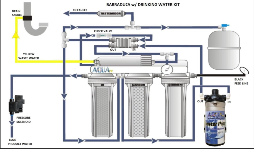
The check valve between the membrane and pressurized tank could go in either place (AWI or AquaFX location) as long as there is one between the pressurized tank and the membrane. This keeps the pressure in the tank from putting back pressure on the membrane. I don't have this check valve as I don't use a drinking water kit.
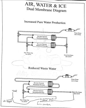
I'm not sure of the function of the second check valve in the AWI diagram (see below). If I had to guess, I'd say It's keep waste water from backing into the DI Bypass when flushing the membrane. My system is designed so I don't need this check valve.
View attachment 32398631
On the AquaFX diagram, the Flush Valve would go on the yellow waste water line. That particular system appears to simply not come standard with the flush valve but, one could easily be added on the waste line (that's what I did with my system).
Either way will be fine. It's just two different ways of accomplishing the same thing. BUT, it leads to a complication with using the AWI as a drinking water kit only (not using / capping off the DI), see below.
Good catch
")
Looking closer at the diagrams, the placement of the T-Fitting on the two units is the BIG difference.
- In the AWI system, the T-Fitting comes AFTER the membrane but BEFORE the ASOV (AWI).
- In the AquaFX system, the T-Fitting comes AFTER the ASOV.
The way the AWI is configured (IMO),
without modification, it can only be used as it was intended...for
both drinking water and RODI. This is because capping off the DI AFTER the ASOV puts pressure on the ASOV and will shut the system down.
If you want the option to make either drinking water or DI water, here is what I would do (you shouldn't need any fittings but, might need some extra RO tubing to make this happen). See diagram below:
- Instead of having the RO water line from the membrane going to the T-Fitting, have it go to the ASOV (green arrow).
- Then, put the T-Fitting on the output oh the ASOV (purple arrow).
- Then, have the other two outlets of the T-Fitting - one going to the Pressure tank (yellow arrow) and the other going to the DI (red arrow).
View attachment 32398666
When you don't want to use DI, simply close the post DI valve (near the words DI Water Out on the AWI diagram). When you want to make DI water, simply open that valve.
Finally, the booster pump you purchased from BRS should work fine.
Hope this makes sense and helps. If we lived closer, I'd come and help you get it worked out.