You are using an out of date browser. It may not display this or other websites correctly.
You should upgrade or use an alternative browser.
You should upgrade or use an alternative browser.
Who wants a cheap, simple, Arduino-based LED controller?
- Thread starter der_wille_zur_macht
- Start date
Hi,Hey Steve, I just read through a post about an Arduino led controller that you said you built and it working. I have Marsaqua lights and just want to ramp them up and down. Everything seems complicated by people wanting to control more. What does your build consist of?
sorry I missed your message
I built the controller using an Arduino, a screen and some LDD drivers. I'd point you towards 'jarduino' as a better option. It uses a touch screen and an Arduino so less components and better design as there's scope to add much more functionality
WOW! I can't believe it's been 3 years since I've logged into the forum! I built a Typhon 1.0 and it's still going strong 3+ years later, and never even put it in a housing. My LED array needs an overhaul, but the controller is still running like new. Still haven't converted my freshwater tank to salt yet, but it may be happening soon now that I bought my own house and have gotten moved. Happy to see this is still evolving. I bet that's plenty for me to catch up on!
You should look at Jarduino, touch screen controller easily added to for other control and monitoringWOW! I can't believe it's been 3 years since I've logged into the forum! I built a Typhon 1.0 and it's still going strong 3+ years later, and never even put it in a housing. My LED array needs an overhaul, but the controller is still running like new. Still haven't converted my freshwater tank to salt yet, but it may be happening soon now that I bought my own house and have gotten moved. Happy to see this is still evolving. I bet that's plenty for me to catch up on!
handychang
New member
hii DWZM. thank you for this thread.. i have built my own diy led controller for may fresh water planted tank. but i have a question. while i select channel 1 menu, the fade time do not change. it only 0:01 and 0:02. but the other channel is work perfectly. i using r20 code from google code link. please your advice.
thank you")
thank you
handychang
New member
hiii its me again.. i have tried setting of the start and end time for channel 1. and the fade duration is work.. thank you every one..
Hello sirOk, I made a google code site to hold the project and uploaded the current prototype version. People who have the prototype PCBs can look here for documentation and to find the bill of materials:
http://code.google.com/p/typhon-reef/
Thank you so much for your efforts to help us my question is I have this arduino here in egypt http://mobile.ram-e-shop.com/cat/mobile/product_info.php/products_id/2147
And I am noob in electronics so if I bought this ardiuno and used the code you put in the link above gonna work with me ?? Or I need to make the same hardware?? And if it work could you please offer a LCD for me to work with from the same site cuz its local here and easy to buy from it with no custom problems ... I am gonna use ldd MW drivers in my LEDs by the way
Duriosracing
New member
There are 3 ways to have it done:Would anyone be able to help me out with the sketches? I have an arduino uno and the all in one setup for button and LCD display as well as a ds1307 RTC. I am way in over my head with the coding and getting it to not throw error codes when uploading.
- spend a couple of years to create a new software
- find a working sketch
- ask someone to spend time to create a sketch
You have to choose the right one
mm.reefs
Member
Would anyone be able to help me out ....
Hi!
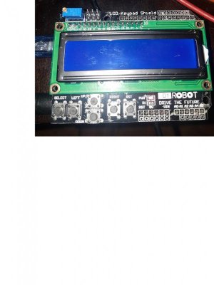
I suggest you to download the Typhon files and check them in Eagle CAD. There you will see all input/outputs to the processor pins. Surely the LCD board you have in the picture don't use the same pins, so you will need to re-map this in the Arduino sketch.
If you want to learn Arduino/PCB design it is a well spent effort. The Typhon board is one of the best designs you will find, not too basic but not to complex. It use many of the Atmega 328 feature that you may need in future projects.
But, if you only want a working Typhon board it will be better just to buy one.
Regards!
Duriosracing
New member
I have all my parts for the board, im surely not going to go out and buy one. I just need some help from someone that sketched the code to help me see what I need to change to get it functioning. I feel all I have left is the button issue as thats the only error I have when verifying.
It's been a while, but I'm Spuzzum, the guy who came up with the single button wire setup to free up more LED channels... I couldn't remember my old email, so now I'm just bmichaelb. With that said... I had a working controller, and a working Arduino IDE with all the libraries needed for Typhon. But now, I'm trying to build another, but the library files at Arduino playground are no more. I specifically need EEPROMVar_01.zip. I found an EEPROMVar.h, but I have no idea how to add it to the libraries. Does anybody know where to find the libraries now?
Thanks.
Edit: Never mind... I just needed to copy it to the C:\Arduino directory. Now I just need to figure out why "'PULLDOWN' was not declared in this scope." Never had that issue before.

Edit: Never mind... it seems Nano's and Uno's are different. This sketch is for Uno, and I'm trying with a Nano. If I remove 'PULLDOWN' from the sketch, it works. At least the button portion... it now errors out on others. I think I'll just pick up an Uno and have done with it.
Thanks.
Edit: Never mind... I just needed to copy it to the C:\Arduino directory. Now I just need to figure out why "'PULLDOWN' was not declared in this scope." Never had that issue before.
Edit: Never mind... it seems Nano's and Uno's are different. This sketch is for Uno, and I'm trying with a Nano. If I remove 'PULLDOWN' from the sketch, it works. At least the button portion... it now errors out on others. I think I'll just pick up an Uno and have done with it.
Last edited:
Welcome back! I have no idea what any of that means lol but @JohnL may be able to help you recover your older usernameIt's been a while, but I'm Spuzzum, the guy who came up with the single button wire setup to free up more LED channels... I couldn't remember my old email, so now I'm just bmichaelb. With that said... I had a working controller, and a working Arduino IDE with all the libraries needed for Typhon. But now, I'm trying to build another, but the library files at Arduino playground are no more. I specifically need EEPROMVar_01.zip. I found an EEPROMVar.h, but I have no idea how to add it to the libraries. Does anybody know where to find the libraries now?
Thanks.
Edit: Never mind... I just needed to copy it to the C:\Arduino directory. Now I just need to figure out why "'PULLDOWN' was not declared in this scope." Never had that issue before.
View attachment 32409039
Edit: Never mind... it seems Nano's and Uno's are different. This sketch is for Uno, and I'm trying with a Nano. If I remove 'PULLDOWN' from the sketch, it works. At least the button portion... it now errors out on others. I think I'll just pick up an Uno and have done with it.
I find a quick conversation with windows copilot can solve just about any programming problem. I ran a 4 channel diy led fixture for the last 2 months off an Arduino Uno. Copilot wrote me the program in about 10 seconds and far more elegantly than what I would have fumbled together.It's been a while, but I'm Spuzzum, the guy who came up with the single button wire setup to free up more LED channels... I couldn't remember my old email, so now I'm just bmichaelb. With that said... I had a working controller, and a working Arduino IDE with all the libraries needed for Typhon. But now, I'm trying to build another, but the library files at Arduino playground are no more. I specifically need EEPROMVar_01.zip. I found an EEPROMVar.h, but I have no idea how to add it to the libraries. Does anybody know where to find the libraries now?
Thanks.
Edit: Never mind... I just needed to copy it to the C:\Arduino directory. Now I just need to figure out why "'PULLDOWN' was not declared in this scope." Never had that issue before.
View attachment 32409039
Edit: Never mind... it seems Nano's and Uno's are different. This sketch is for Uno, and I'm trying with a Nano. If I remove 'PULLDOWN' from the sketch, it works. At least the button portion... it now errors out on others. I think I'll just pick up an Uno and have done with it.
I've never used Copilot, and only heard of it recently, or at least mentioned... I have no idea what it does. - Quick google tells me it's an AI thingamajig.I find a quick conversation with windows copilot can solve just about any programming problem. I ran a 4 channel diy led fixture for the last 2 months off an Arduino Uno. Copilot wrote me the program in about 10 seconds and far more elegantly than what I would have fumbled together.

I wound up opening a thread on the Arduino forums and they helped me out. It came down to libraries. I still don't have a working EEPROMVar,h though... the one I was able to find gave way too many errors, so I wound up editing that part out of the sketch. I actually came across another version of the sketch that just used the regular EEPROM as well, so I figured it wouldn't hurt. I also needed a proper Button library... found one on Github, linked by another thread.
Truth be told, I really just want a single relay channel without the fade functions, to control a grow panel, read the ambient temperature and humidity. I'll work the humidity part in to the sketch later... I already found some code. I could have just created a new sketch piecing together example code that starts and stops things using the clock, but by the sounds of it, the Arduino has issues keeping time for long periods. There's a grow tent controller by a company called AC infinity that has a fade function, and from what I've read, users need to fiddle with it or the fade function won't actually work when scheduled. But this script doesn't have that problem... I'm guessing it's because it resets at midnight. This seems to be the best script to work with.
Well, after fiddling with all that, I just came across a thread on thcfarmer with a working script that looks as if it's built on the script in this thread. Strangely, it still uses EEPROMVar, but it doesn't error out. So either the EEPROMVar.h I have is different than the one used in this thread, or I just don't know. The link for the file at the top of the script no longer works, so I can't just grab a new one. It literally took forever to find a copy.
But... seeing how it does work with this guy's script, I figured I'd link his script in case anyone wants to build a new one. The only difference is it has the Adafruit RGBLCD shield, which is similar to the Deuligne shield I posted a schematic of way back when, that uses less Arduino pins, and all buttons connected on a single pin... if I remember correctly, using ADC Keys. He has 6-channel scripts, with and without the DHT11 temperature and humidity sensor, as well as a 12-channel script. As I say, they look identical to this thread, so they shouldn't be too difficult to modify if you need.
Although I don't have a tank, I was originally building a grow light back in 2012 when I participated in this thread. My plan was to use all the various colours needed, then fade up starting with blues, then fade out ending in reds. But then I realized all those Mean Well drivers's current intakes added up to more than my breaker... lol. So now I'm just using Warm Whites and Cool Whites. I originally thought of editing out the fade portion of the script, but being able to adjust one over the other would have it's benefits for simulating the seasons... veg is more blue, flower is more red.
Any way... that's for another forum. But here's the code and links...

 github.com

 www.adafruit.com
Cheers.
Actually looking in my Arduino libraries folder, I only have EEPROMEx right now... I already deleted the copy I searched for. So, this script works with EEPROMEx, which has EEPROMVar.h.
Edit: Adding a hard copy of the non-DHT11 version, in case someone finds this thread at a later date, and the link becomes dead.
But... seeing how it does work with this guy's script, I figured I'd link his script in case anyone wants to build a new one. The only difference is it has the Adafruit RGBLCD shield, which is similar to the Deuligne shield I posted a schematic of way back when, that uses less Arduino pins, and all buttons connected on a single pin... if I remember correctly, using ADC Keys. He has 6-channel scripts, with and without the DHT11 temperature and humidity sensor, as well as a 12-channel script. As I say, they look identical to this thread, so they shouldn't be too difficult to modify if you need.
Although I don't have a tank, I was originally building a grow light back in 2012 when I participated in this thread. My plan was to use all the various colours needed, then fade up starting with blues, then fade out ending in reds. But then I realized all those Mean Well drivers's current intakes added up to more than my breaker... lol. So now I'm just using Warm Whites and Cool Whites. I originally thought of editing out the fade portion of the script, but being able to adjust one over the other would have it's benefits for simulating the seasons... veg is more blue, flower is more red.
Any way... that's for another forum. But here's the code and links...
GitHub - AvidLerner/GrowGreen: LED Light Controller for high power DIY LED lights for dimming and turning on/off
LED Light Controller for high power DIY LED lights for dimming and turning on/off - AvidLerner/GrowGreen
github.com
Adafruit I2C Controlled + Keypad Shield Kit for 16x2 LCD
We really like the range of LCDs we stock in the shop, such as our classic blue & white and the fancy RGB negative and RGB positive. Unfortunately, these LCDs require quite a few digital ...
www.adafruit.com
Cheers.
Actually looking in my Arduino libraries folder, I only have EEPROMEx right now... I already deleted the copy I searched for. So, this script works with EEPROMEx, which has EEPROMVar.h.
Edit: Adding a hard copy of the non-DHT11 version, in case someone finds this thread at a later date, and the link becomes dead.
Attachments
Last edited:
Well, after playing around with the Grow sketch, I found my lack of coding knowledge unable to change things the way I wanted. For instance, the coder shortened things with a single command, but letting it fill in which item to command...
I prefer where each individual item is separated... like the original script. It just makes adding things like a relay a lot easier, or to label the Channel ID in the menu as which LEDs I'm actually controlling by colour, not by number on a list.
Well... I just figured out the original Typhon... or at least to get it to use the regular EEPROM, not EEPROMVAR.h.
I changed...
To...
Then due to the TwoWire errors, ('class TwoWire' has no member named 'send'; did you mean 'end'?), I changed 'Wire.send' to 'Wire.write', and 'Wire.receive' to 'Wire.read'. It now compiles again. Now I can use 'my' version, or at least one of them. It'll also be easier to work in a pump relay.
Code:
void readSettings() {
  int EEPROM_address = 0;
  for (byte i = 0; i < LED_channels; i++) {
    EEPROM.get(EEPROM_address, LED[i]);
    if (LED[i].versionCheck != 9898) {
      // Set default values for the settings and save them to EEPROM
      LED[i].versionCheck = 9898;
      switch (i) {
        case 0:
          LED[i].StartMins    = 750;
          LED[i].PhotoPeriod  = 720;
          LED[i].Max          = 100;
          LED[i].FadeDuration = 15;
          break;
        case 1:
          LED[i].StartMins    = 720;
          LED[i].PhotoPeriod  = 720;
          LED[i].Max          = 100;
          LED[i].FadeDuration = 15;
          break;
        case 2:
          LED[i].StartMins    = 720;
          LED[i].PhotoPeriod  = 720;
          LED[i].Max          = 100;
          LED[i].FadeDuration = 15;
          break;
        case 3:
          LED[i].StartMins    = 720;
          LED[i].PhotoPeriod  = 720;
          LED[i].Max          = 100;
          LED[i].FadeDuration = 15;
          break;
      }
I prefer where each individual item is separated... like the original script. It just makes adding things like a relay a lot easier, or to label the Channel ID in the menu as which LEDs I'm actually controlling by colour, not by number on a list.
Well... I just figured out the original Typhon... or at least to get it to use the regular EEPROM, not EEPROMVAR.h.
I changed...
Code:
// Variables making use of EEPROM memory:

EEPROMVar<int> oneStartMins = 750;      // minute to start this channel.
EEPROMVar<int> onePhotoPeriod = 720;   // photoperiod in minutes for this channel.
EEPROMVar<int> oneMax = 100;           // max intensity for this channel, as a percentage
EEPROMVar<int> oneFadeDuration = 60;   // duration of the fade on and off for sunrise and sunset for
                                       //    this channel.
EEPROMVar<int> twoStartMins = 810;
EEPROMVar<int> twoPhotoPeriod = 600;
EEPROMVar<int> twoMax = 100;
EEPROMVar<int> twoFadeDuration = 60;

EEPROMVar<int> threeStartMins = 810;
EEPROMVar<int> threePhotoPeriod = 600;
EEPROMVar<int> threeMax = 100;
EEPROMVar<int> threeFadeDuration = 60;

EEPROMVar<int> fourStartMins = 480;
EEPROMVar<int> fourPhotoPeriod = 510;
EEPROMVar<int> fourMax = 100;
EEPROMVar<int> fourFadeDuration = 60;

// variables to invert the output PWM signal,
// for use with drivers that consider 0 to be "on"
// i.e. buckpucks. If you need to provide an inverted
// signal on any channel, set the appropriate variable to true.
boolean oneInverted = false;
boolean twoInverted = false;
boolean threeInverted = false;
boolean fourInverted = false;

/*
int oneStartMins = 1380;      // minute to start this channel.
int onePhotoPeriod = 120;   // photoperiod in minutes for this channel.
int oneMax = 100;           // max intensity for this channel, as a percentage
int oneFadeDuration = 60;   // duration of the fade on and off for sunrise and sunset for
                                       //    this channel.
int twoStartMins = 800;
int twoPhotoPeriod = 60;
int twoMax = 100;
int twoFadeDuration = 15;

int threeStartMins = 800;
int threePhotoPeriod = 60;
int threeMax = 100;
int threeFadeDuration = 30;

int fourStartMins = 800;
int fourPhotoPeriod = 120;
int fourMax = 100;
int fourFadeDuration = 60;
*/
To...
Code:
// Variables making use of EEPROM memory:

/*
EEPROMVar<int> oneStartMins = 750;      // minute to start this channel.
EEPROMVar<int> onePhotoPeriod = 720;   // photoperiod in minutes for this channel.
EEPROMVar<int> oneMax = 100;           // max intensity for this channel, as a percentage
EEPROMVar<int> oneFadeDuration = 60;   // duration of the fade on and off for sunrise and sunset for
                                       //    this channel.
EEPROMVar<int> twoStartMins = 810;
EEPROMVar<int> twoPhotoPeriod = 600;
EEPROMVar<int> twoMax = 100;
EEPROMVar<int> twoFadeDuration = 60;

EEPROMVar<int> threeStartMins = 810;
EEPROMVar<int> threePhotoPeriod = 600;
EEPROMVar<int> threeMax = 100;
EEPROMVar<int> threeFadeDuration = 60;

EEPROMVar<int> fourStartMins = 480;
EEPROMVar<int> fourPhotoPeriod = 510;
EEPROMVar<int> fourMax = 100;
EEPROMVar<int> fourFadeDuration = 60;
*/

// variables to invert the output PWM signal,
// for use with drivers that consider 0 to be "on"
// i.e. buckpucks. If you need to provide an inverted
// signal on any channel, set the appropriate variable to true.
boolean oneInverted = false;
boolean twoInverted = false;
boolean threeInverted = false;
boolean fourInverted = false;


int oneStartMins = 1380;      // minute to start this channel.
int onePhotoPeriod = 120;   // photoperiod in minutes for this channel.
int oneMax = 100;           // max intensity for this channel, as a percentage
int oneFadeDuration = 60;   // duration of the fade on and off for sunrise and sunset for
                                       //    this channel.
int twoStartMins = 800;
int twoPhotoPeriod = 60;
int twoMax = 100;
int twoFadeDuration = 15;

int threeStartMins = 800;
int threePhotoPeriod = 60;
int threeMax = 100;
int threeFadeDuration = 30;

int fourStartMins = 800;
int fourPhotoPeriod = 120;
int fourMax = 100;
int fourFadeDuration = 60;
Then due to the TwoWire errors, ('class TwoWire' has no member named 'send'; did you mean 'end'?), I changed 'Wire.send' to 'Wire.write', and 'Wire.receive' to 'Wire.read'. It now compiles again. Now I can use 'my' version, or at least one of them. It'll also be easier to work in a pump relay.
Forgot to mention about the buttons...
Change...
To...
Change...
Code:
// create the buttons
Button menu = Button(12,PULLDOWN);
Button select = Button(13,PULLDOWN);
Button plus = Button(14,PULLDOWN);
Button minus = Button(15,PULLDOWN);
To...
Code:
// create the buttons
Button menu = Button(12);
Button select = Button(13);
Button plus = Button(14);
Button minus = Button(15);Well crap... I just found the actual EEPROMVar.h and Button library used for the original script. I didn't use the Button library, but c/p'd the EEPROMVar.h to a EEPROMVar folder in the Arduino library folder. And... it compiles just fine. Still needed to change the Wire commands though.

 codebender.cc
codebender.cc
codebender.cc
Edit: Never mind... for some reason, the text is garbled when trying to set the Channel 1 Start, End, Fade and Max settings using the menu, but Channel 2 looks fine. Really not sure why. Gone back to using the regular EEPROM, it just won't save settings to the chip itself. Oh well... unless I missed a later version in the thread, but this version says...
So maybe that was a bug still being worked on at the time.
Edit 2: Well, I reloaded the script to see if the time menu was fine at least, then I'd just set the start/end/fade times using the PC, then set the current time using the menu. But after loading the script again... there's no more garbled text on Channel 1 anymore. Ghost in the machine I guess.
Code:
#include <Arduino.h> //changed from WProgram.h
#include <EEPROM.h>
/*
   www.alexanderbrevig.com
   AlphaBeta
*/

class EEPROMAddressCounter {
protected:
  static int availableAddress;
};
int EEPROMAddressCounter::availableAddress = 0;

template<typename T>
class EEPROMVar :
public EEPROMAddressCounter {
public:
  static const byte IS_INITIALIZED = B10101010;
  EEPROMVar(T init) {
    address = availableAddress;
    var = init;
    restore();
    availableAddress += sizeof(T) + 1; //make room for the is initialized flag
  }
  operator T () {
    return var;
  }
  EEPROMVar &operator=(T val) {
    var = val;
    save();
  }
  void operator++(int) {
    var += T(1); //cast for safety
    save();
  }
  void operator--(int) {
    var -= T(1); //cast for safety
    save();
  }
  void operator++() {
    var += T(1); //cast for safety
    save();
  }
  void operator--() {
    var -= T(1); //cast for safety
    save();
  }
  template<typename V>
    void operator /= (V divisor) {
    var = var / divisor;
    save();
  }
  template<typename V>
    void operator *= (V multiplicator) {
    var = var * multiplicator;
    save();
  }
protected:
  void save(){
    union {
      byte raw[ sizeof(T) ];
      T data;
    } writer;
    writer.data = var;
    for (byte i=0; i<sizeof(T); i++) {
       EEPROM.write(address + 1 + i, writer.raw[i]);
    }
  }
  void restore(){

    byte init = EEPROM.read(address);

    if (init!=EEPROMVar::IS_INITIALIZED) {
      //it was not initialized
      EEPROM.write(address,EEPROMVar::IS_INITIALIZED);
      union {
        byte raw[ sizeof(T) ];
        T data;
      } writer;
      writer.data = var;
      for (byte i=0; i<sizeof(T); i++) {
         EEPROM.write(address + 1 + i, writer.raw[i]);
      }
    }
    //read from EEPROM
    union {
      byte raw[ sizeof(T) ];
      T data;
    } reader;
    for (byte i=0; i<sizeof(T); i++) {
       reader.raw[i] =  EEPROM.read(address + 1 + i);\
    }
    var = reader.data;
  }
  T var;
  int address;
};
Arduino Cloud IDE - Codebender
Arduino IDE in the Cloud. Codebender includes a Arduino web editor so you can code, store and manage your Arduino sketches on the cloud, and even compile and flash them.
Arduino Cloud IDE - Codebender
Arduino IDE in the Cloud. Codebender includes a Arduino web editor so you can code, store and manage your Arduino sketches on the cloud, and even compile and flash them.
Edit: Never mind... for some reason, the text is garbled when trying to set the Channel 1 Start, End, Fade and Max settings using the menu, but Channel 2 looks fine. Really not sure why. Gone back to using the regular EEPROM, it just won't save settings to the chip itself. Oh well... unless I missed a later version in the thread, but this version says...
// Current work in progress:
// - store all LED variables in EEPROM so they are not reset by a loss of power
So maybe that was a bug still being worked on at the time.
Edit 2: Well, I reloaded the script to see if the time menu was fine at least, then I'd just set the start/end/fade times using the PC, then set the current time using the menu. But after loading the script again... there's no more garbled text on Channel 1 anymore. Ghost in the machine I guess.
Last edited:
Well... I just came across reef-pi, and it looks like a better project for what I need. It even has pH monitoring and adjusting built in, and I should be able to modify the sources to add and subtract a few things in the GUI. And I can add a touch screen display.
Also, not sure what happened, buy after posting the link to that codebender project, the very next day the link goes 404. I hope I didn't post something I wasn't supposed to.
Also, not sure what happened, buy after posting the link to that codebender project, the very next day the link goes 404. I hope I didn't post something I wasn't supposed to.
Similar threads
- Replies
- 0
- Views
- 1K
- Replies
- 6
- Views
- 2K
- Replies
- 39
- Views
- 713
- Replies
- 23
- Views
- 3K