SimonSKL
New member
Here is a photo of the test harness that Roberto from Reefangel constructed. Hopefully he does not mind me posting it here. As they say, a picture is worth a thousand explanations :eek2:
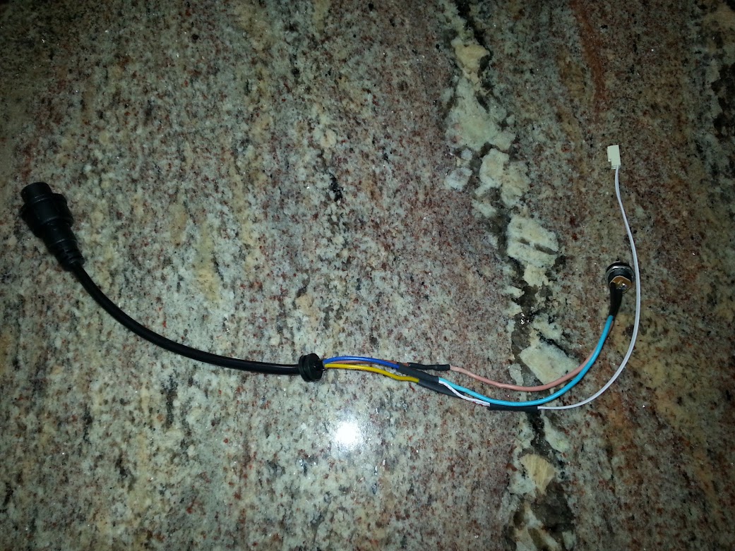
In the above photo:
the blue wire appears to be ground
the yellow wire is the +5V analog control signal (labelled VA on the controller's board)
the brown wire is the +24V DC
The white wire is the connector for the 0-10V analog connected between ground and +5V analog input to the pump. Remember you have to keep the signal from your device toa maximum of 5 volts.
Dennis
Any updates from RA folks who are trying to control this pump?

") I'm going to try one on my 125 and see how it does.
I'm going to try one on my 125 and see how it does.