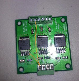
DIY LED driver for reef lighting

I believe that I remember reading in this thread that it was possible to get more than 1 amp through a string of LEDs. Was it just a matter of running two drivers to the same string? For example, have each driver outputting 750mA and connect them to one string for a total of 1.5A running through the string of LEDs. Am I way off on this?

Scratch that, found the answer.


I think that post 1503 is what you are looking for.
 
I believe that I remember reading in this thread that it was possible to get more than 1 amp through a string of LEDs. Was it just a matter of running two drivers to the same string? For example, have each driver outputting 750mA and connect them to one string for a total of 1.5A running through the string of LEDs. Am I way off on this?

Scratch that, found the answer.

Yes, That's correct. I have already have a setup running which drives a string of 6 leds with more than 1 amp with the output of 2 drives wired together. You can even drive it at > 2 amps with 3 drivers.

+ve terminal of the drivers is common, so you can connect the +ve of the LED string to the +ve of any one of the drivers and connect the -ve of both the drivers to the -ve of the LED string.

Actually, I am driving 7 XM-Ls per string at 1.5A. Since the forward voltage is 3.1V at 1.5A, your drivers will heat up while burning the extra volts if you have only 6 XM-Ls per string. I have set my supply voltage at 22.2V ((7*3.1)+0.5).
 
Last edited:
I would connect the + terminal to both drivers. I don't remember the spec on the 3 driver board, but my board was designed so the traces only carry 1 amp. If you try and drive the string with 1.5 amps it could act like a fuse and melt the trace (or only get hot).

As an alternative you could directly connect the + of the LED string to the power supply since it is fed directly from the 24 volts. I am actually thinking of doing this and adding the 1 ohm resistor in series to measure current.
 
hey guys. I finished putting together a board, but something is wrong. I have 6 xp-e blue in the string. The problem I have is that they don't light up. but if I connect a wire from the ground to the L- they light up. also I don't have the pwm connect when i connect the ground. I'm I doing some wrong? Is there a way to figure out what I did wrong.
 

Attachments

  • IMAG0121.jpg
    IMAG0121.jpg
    103.1 KB · Views: 13
When you short L- to ground you are bypassing the CAT - this is not recommended it could blow the LEDs. If the power supply is set to supply a lot of excess voltage (and therefore current) it will blow the LEDs.

Is the PWM at +5 in normal operaion?
Can you measure the voltage of each pin when you have it on?
 
I had problems on one board in which two of the CAT's wouldn't work. Checking all the traces I found that the pwm traces from the connector to the CAT was bad.
 
Guys, I have been running strings of 7 cree xm-l with 2 cat4101 drivers in parallel for about a month now. I drive them at 1500 ma. While switching off today, I noticed that one xm-l led had burned out. It is lighting up but has a black center (lights up like a solar eclipse). Any idea what went wrong? Any checks I should do before replacing it with a spare? I have 3 other strings which are fine ( as of now).
 
I would double check the current going through that string, but I doubt it is a problem. Is there something on/in the lens or is it in the die?

[EDIT]
You may need to use a really low current so you don't blind yourself :) Maybe the diode check function on your meter.
 
I have no lens on the LEDs and I checked the currents when I hooked up the strings initially. Could be just a bad LED. I had actually hooked up my DIY PWM circuit when I noticed the problem. I had dimmed the LEDs to 5%.

Anyways, it's almost 11pm now and my wife would kill me if I got out the screwdriver and multimeter now. :) Lucky it's a Saturday tomorrow! I'll post my findings tomorrow. Just worried as those things cost $10 a piece.

BTW, my PWM circuit is AVR micro-controller based and on a breadboard right now. Don't know if that's a problem! :(
 
I have the psu set at 20.3v. Do you have to have exactly 5v to the 5v input? Because I'm using 4.5v for right now until I build the controller. I measured the pins and I get 3.5v in pin 1 and 4.5v in pin 2, pins 3 & 4 none and pin 5 8.17v.

edit sorry I get .5mv in pin3 and .7mv in pin4.
Yes I have the pwm plugged in with +3 v
 
Last edited:
I have the psu set at 20.3v. Do you have to have exactly 5v to the 5v input? Because I'm using 4.5v for right now until I build the controller. I measured the pins and I get 3.5v in pin 1 and 4.5v in pin 2, pins 3 & 4 none and pin 5 8.17v.

edit sorry I get pin3 .5mv and pin4 is .7mv

The input to CAT can be between 3.0 to 5.5V according to the datasheet. The input at pin 2 would act as a reference for the PWM. i.e pin 1. If you are not using PWM, connect pin 1 and pin 2 to check if it works. If you are using PWM, use the same supply voltage to pin2 as your pwm circuit. I would not connect L- to ground ( as you mentioned in your previous post). That would be directly connecting the LEDs to the power supply.
 
Pin 4 is ground is that 0.5 millivolt or 0.5 volts assuming the first OK good. Pin 4 should be about 1.2 volts this goes to Rset at least when the LEDs are on. What size resistor is in there for RSet? Do any of the circuits work?
as Nirgos suggest connect 1 and 2 and see if it lights up.
Pin 5 should run .5-1 volt and the rest is dropped across the LEDs. Right now 20.3 - 8.17 about 12 volts is driving the LED which is not enough to light them.
 
I tested another board i did and it works as it should. I think I accidentally switch the c1 with c4 components. With this board I'm using 549ohms for the xp-g cw. Who can I test to make sure that it's out putting the right ma.
 
I tested the 5 pins and these are the numbers I get. ( this is the good board with the 549 ohm resistor)

pin 1 4.16 v
pin 2 4.16 v
pin 3 2.0 mv
pin 4 1.19 v
pin 5 .444 v
 
nirgos; You need to re-check the current. Something may have made it go higher. What you describe is a 'burned-up' LED. If the current isn't the issue then the cooling definitely is. Running LEDs at 1.5A means you're cooling has to be very good. With emphasis on very.

Have you got a picture of your LEDs on your heat-sinking?
 
TheFishMan65, nirgos Thanks for help guys I should have checked the other board before I posted. I'm new to this type of stuff and I greatly appreciated your help.

Again Thanks.
 
No. When I was taking the reading with the multimeter I touched two of the pins together and killed it. This was just a test run for me. Since I'm new to this kind of stuff I thought I would start small. I placed another order with Mouser.
 
I remember the LM3409(HV) being mentioned a few times here but don't remember anyone actually following up to say if they use it and how it worked for them. I'm starting to work on a board for it, so if anyone knows of any gotchas, please let me know :).

My goal is fairly simple: reference design on a small PCB with the required amplification for 5V PWM/Analog dimming control (so that it is useful for Arduino based controllers). Nothing fancy really, but the chip looks very nice so I wanted to give it a try. I'll let you guys know when I have some schematic ready.
 
terahz, what do you see as the advantage of that design over the CAT? At a quick look it seems to have more external parts and cost a little more.
 
Back
Top