Durso standpipe?

Prestigious, really appreciate your ideas dude, it was my mistake, I really didn't want to go to the bean animal style to begin with, I was totally set on keeping the layout I already have. But now it seems like this is the right method for the style of tank I want, I didn't think I would be drilling 4 holes in my tank that's for sure. But I'm worried that if I don't I'll regret later down the line. Thanks for your input nonetheless, I'll let you know how it all goes, for sure is gonna be a big headache to do all this, but hoping it will be worth it in the long run.
 
........Okay

So where were we.

I'm going to tear out the overflows in there, anything I should be aware of here, just going to exacto knife down the silicon and pull out, then scrape any excess silicone off.

Leave the bottom corners of the overflows in place. This is to prevent damage to the inner seal of the tank. A shallow sand bed will hide the left overs.

Got the bulkheads and plugs for the bottom.

Got a quote from Melevs for an overflow box.

Now just need to know what size holes do you reccomend for the 3 overflows, and also what size for return?
1" Bulkheads, at full siphon, (the system as designed) will handle from 1200 to 1500 gph, depending on the pipe size used, and the length of the drop (pipe size involves friction loss) The max theoretical for a 1" bulkhead with a 24" drop is ~ 1660 gph.

And, placement of the holes. Think 12" apart length ways, can the 2 wet siphons be put on either side and emergency be placed in middle like on the drawing?
The holes can be placed anywhere you want them length wise, the only proviso is that they be 1 x the hole diameter (edge to edge) from each other and the glass edges. See above for additional.

Lastly, is there any where I can try that drills glass, not comfortable doing it myself?
See above (my last post.)
 
That's all good information. Going to call around a few glass shops tomorrow.

I plan on using a Reeflo snapper dart, so can change between the 2 flows if needed.

There outputs are 4300/2600gph, that's before a 5ft climb and a few corners and there'll be a small loss with some of the return going back to the fuge. So maybe if I go with the 4300 setting I can have a dual return.

How much flow can you get with 1.25" I was aiming for 10x turnover, as has been suggested to me.
 
I would run the main return at 1800 gph. More is not going to hurt anything at all. The snapper impeller/head, probably would not get there. With the dart impeller, you will have some excess, most likely. It seems that you are going to go over the river and through the woods with the plumbing, so it is going to be best to have more pump than it seems would be needed. It can be pinned down rather closely, mathematically. (preferred method for choosing the pump that will be most efficient for the job) Just for GP, I would run 2" pipe on the output--and bring the friction loss down by 2/3 approximately.

Theoretically, a 1.25" bulkhead with a 5' drop will flow ~4100 gph. (not accounting for friction loss.) With 1" bulkhead, and a 5' drop, the max theoretical is ~ 2600 gph. With larger pipe, on the 1" bulkhead, such as 1.25" or 1.5" you would get closer to the max, due to lower friction loss. With the open channel it is pretty much obligatory to go up to 1.25" or 1.5" for the most quiet operation. (this system is dead silent--if set up right.) A 1.5" bulkhead will theoretically do ~ 6000 gph with a 5' drop.

Along with the "over the river and through the woods" with the return, the drains are going to do the same thing. You need to know that horizontal runs in the drain lines will likely undo your efforts. The horizontal runs can cause the drain to air lock, (trapped air) and prevent the siphon from fully starting, and throw the whole system out of whack. The drain lines need to be angled down, 45° is preferred, thought straight down is best. (this applies to any drain system you would use.)
 
Great info, I wouldn't have thought of the horizontal drains, I will angle them.

So I'm going to use 1" bulkheads.
1.25" pipe on the 2 main siphon drains
1.5" pipe on the emergency? (The emergency is the open channel, correct?
I'll use these bulkheads that recquire a 1.88" installation hole.
http://www.bulkreefsupply.com/bulkhead-schedule-80-slip-x-thread-slip-on-the-flange-head-side-2.html
These install to the hole using the thread, and then the inlet pipe just slides into the bulkhead?

So the holes I should drill 1.88" from the black trim bottom. (1 x diameter of hole (1.88)) is that correct?

Sound like a plan, I've tried to follow closely.


Before anything else. I will encourage you NOT to use schedule 80 bulkheads. There is no reason to use them--none. ABS Black bulkheads are absolutely, without reservation, more than enough for our use. Installed correctly, they do not leak, or cause any type of problem.

On the other hand, Schedule 80 bulkheads, have a smaller inside diameter, and reduces the flow capacity of the whole system.

Before going to specific dimensions, you need to make that decision, because the hole size is different. You can get the ABS bulkheads from glass-holes.com, you can also get the hole saws and other supplies you may need. I know BRS sells this stuff too, but they ain't gunna send you candy. Come on now, I know you want the candy. ;)

We don't measure from the bottom of the trim. So your holes would have been a bit low, depending on where you measured to. (center or edge of the hole)
 
Last edited:
That's good to know, ABS it is. I'd already seen that, the hole needed for 1" bulkhead using ABS is 1.66" so a hole at 1.7" would do it.

So where do I measure from, the very top edge of the tank (top edge of black trim)? To the centre, or top edge of the hole?

Also, did I read right that 2" return pipe is recommended? Just sounded quite big. Would you just use another bulkhead for the return? New to the plumbing aspect, so just trying not to miss something.

If you use another bulkhead here, what size for 2" pipe?
 
Again, first before anything else, lol, ;) a 1" ABS bulkhead uses a 45mm hole saw. (1.75" hole.) BRS makes things complicated by TMI. ;)

The hole CENTERS should be at least 2.75" down from the TOP edge of the GLASS. This is well within the 1x rule: The TOP edge of the HOLE, will be 1.875" down from the TOP edge of the GLASS.

You may be thinking the h*ll you say, where is the top edge of the glass on a rimmed tank. Well the TOP edge of the GLASS, is 1/2" down from the TOP of the TRIM (the very top of the tank.) K got that?

The BOTTOM of the TRIM on the outside of the tank, is 1" down from the TOP of the Glass. K got that? You may think what the heck is up with the caps lock. What I just said is important, or you won't get what I am going to say next, as I am not going to use caps, and you will be able to find the location several different ways.

The top of the weir, is placed 1" down from the top edge of the glass. This hides the water line above the bottom of the outside trim. The water level in the overflow will be ~ 1" lower than that, or around the top of the down turned elbows for the drains, ~3/4" above the hole center line.

It is not a bad idea to drop the holes down another 1/2" give or take, as this will draw the up turned elbow on the dry emergency down below the top edge of the weir. This will increase the length of the drop inside the overflow box, but with sufficient length it should not cause noise.

In a power out situation you will have around 1" of water drain from the overflow, and perhaps 1" out of the main tank, as long as your return outlet is within 1" of the water surface. Armed with that information and (pi x radius squared x length of the siphon pipe)/231, plus volume in the skimmer, you can fairly accurately determine the amount of power out drain down and adjust your sump volume accordingly.

On the return: It is common practice, though some try to debate it, to up-size the return plumbing one pipe size above the actual size of the pump outlet. So with the dart, you would want to use a 2" pipe on the output. Any larger than that, and you would want to increase the inlet piping accordingly, to help prevent cavitation, because this is an external pump, and the inlet is 2". The 2" inlet pipe could appear as a restriction at the pump inlet, if the outlet pipe was over 2". The inlet and outlet size has nothing to do with the plumbing size, however, the needs of the system determine that.

The idea here is to reduce the friction loss to a point where it IS almost negligible, but that often will take some pretty large pipe, depending on the flow rate. One size up generally reduces the friction loss by ~ 2/3.

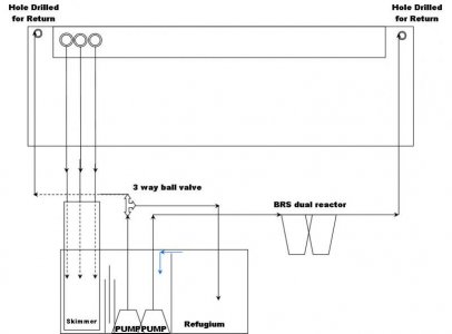
I run a single line up over the back of the tank, keeping it simple, and allowing other parts of the system to do their job, e.g. the power heads. You don't need to use a bulkhead.

This should give you some idea:

337-7.jpg


However your drains system look like the graphics in Bean's article and thread.
 
Owwwww My head hurts.

Okay, I think I'm still following.

So, as far as depth of the holes, with the ABS bulkhead, drilling a 1.75" hole, the centers of the holes should be 3.25" below the top edge of the black trim, (2.75+0.5 -{the gap between trim edge and glass edge})

Originally I was under the belief that I needed to spread those holes over the length of the back of the tank to aid surface skimming? after seeing that picture, I'm now thinking that its the actual weir that does the surface skimming and that once the surface water has gone into the overflow box its going to find the drain?

So if there's no reason to spread them out like my drawing, just put them all together on one end? - If so, now how far apart do I drill the holes from each other, (2.75"?)

Is the Reeflo a good pump to go with? do you have another suggestion? I'm kinda interested in seeing if there is a good internal pump but not sure there is one with enough power, that will not get too hot.

If I stick with the Reeflo, I'll have to make a shelf for it to sit on above the sump, and then run the inlet down to the return chamber. Would that work.

Thanks
 
Last edited:
Prestigious, really appreciate your ideas dude, it was my mistake, I really didn't want to go to the bean animal style to begin with, I was totally set on keeping the layout I already have. But now it seems like this is the right method for the style of tank I want, I didn't think I would be drilling 4 holes in my tank that's for sure. But I'm worried that if I don't I'll regret later down the line. Thanks for your input nonetheless, I'll let you know how it all goes, for sure is gonna be a big headache to do all this, but hoping it will be worth it in the long run.

No prob, glad your going with beaaaan, especially if your wanting to push that much flow.

Uncleof6 is right about the friction loss. I might of been missleading in saying it is "neglegible". I was only referring to my particular setup I was talking about. You can make it "near" neglegible by having adequite pipe sizing. I sometimes throw the word negligible around a lot when I do pump sizing at work because when your dealing with 200' of verticle/dynamic head, my frictional head tends to be <5' equivalent. The pumps in our aquariums deal with very small amounts of head (well most, check your pump curve) so people who squeeze 2000GPH through 1" pipe with 90 deg fittings and crap will see a good amount of friction loss.

I would use 1.5" or 2" on that snapper pump for your return and make sure your intake on the pump is larger, as Uncle had suggested. Pump cavitation is not a fun problem to have.
 
Is the Reeflo a good pump to go with? do you have another suggestion? I'm kinda interested in seeing if there is a good internal pump but not sure there is one with enough power, that will not get too hot.

Those Mag pumps are pretty popular. To get the flow you want you might have to run 2 of them though.... which might not be a terrible thing. You would be able to run a return to each end of the tank for better circulation AND you would have a back up/fail safe. I bring this up because my Reeflo return pump got clogged some time last week and dropped my oxygen lvls extremely low resulting in the death of my biggest angel. Im now finally going to bite the bullet and get some vortechs as a result. It was my fault though for not having a strainer on the pump inlet, using stupid rubble rock (bad idea), and prolonging the servicing of the pump.
 
Originally I was under the belief that I needed to spread those holes over the length of the back of the tank to aid surface skimming? after seeing that picture, I'm now thinking that its the actual weir that does the surface skimming and that once the surface water has gone into the overflow box its going to find the drain?

Holes can be wherever you want them. Forget the holes for a minute and think about water level rising to meet a level wier, no matter where the holes are it will cascade over the wier evenly,,, its just very important that you get that wier level.


If I stick with the Reeflo, I'll have to make a shelf for it to sit on above the sump, and then run the inlet down to the return chamber. Would that work.

The pump would have to be primed. These pumps are not self priming either so if it loses prime for whatever reason then you would have to prime it again.... Uncle can correct me if I am wrong but if the pump cuts off it will break siphon from the air that it will intake from the return line. I have never run a Reeflo this way nor have I seen people do it so I dont have too much info to offer on this. I can say if at all possible you should try to make the pump flooded instead of primed for reliability reasons. If your going with the external overflow then you should have room behind the tank to put your pump parallel to the sump and add on a 90deg fitting.
 
Thanks Prestigous,

Yeah, I think I'm leaning towards the Mag Drive, That would simplify the return plumbing a lot, and like you say, I then can have a return at each end of the tank. I intend on using powerheads too, but If I can get good flow out of the return, it takes the load off the powerheads a bit.

Maybe a Mag 18, and Mag12, will give 3000GPH of flow, but suspect with all the plumbing, it will be more like 2000 once it hits the tank?

The other thing to consider is that I want to run a BRS Dual reactor, does that go in line, or is that something that has a separate pump running water from the return chamber to the reactor and then back to the return chamber?

Changed the drawing, read all of beans site, and first couple of pages of his thread, so, going to position the drains all together at one end to make the drain plumbing simpler.
 

Attachments

  • Plumbing Reef V2.jpg
    Plumbing Reef V2.jpg
    32.3 KB · Views: 24
Owwwww My head hurts.

Okay, I think I'm still following.

So, as far as depth of the holes, with the ABS bulkhead, drilling a 1.75" hole, the centers of the holes should be 3.25" below the top edge of the black trim, (2.75+0.5 -{the gap between trim edge and glass edge})

Yes. Adding a bit more, say--1/2", will lower the level of the dry emergency inlet, giving you bit more wiggle room.

Originally I was under the belief that I needed to spread those holes over the length of the back of the tank to aid surface skimming? after seeing that picture, I'm now thinking that its the actual weir that does the surface skimming and that once the surface water has gone into the overflow box its going to find the drain?
Where the three holes are, is not important to the design or function. They can be at one end, the other end, the middle, or spread evenly across the back.

The weir does the skimming, everything else just gets the water to the sump.

So if there's no reason to spread them out like my drawing, just put them all together on one end? - If so, now how far apart do I drill the holes from each other, (2.75"?)
The rule for hole spacing is the same. 1x the hole diameter from edge of the hole to edge of the next hole, minimum. As long as everything fits, you don't need the holes any further apart than that. The only thing inside the tank will be the elbows, on the bulkhead, so measuring the elbow can give you an idea.

Is the Reeflo a good pump to go with? do you have another suggestion? I'm kinda interested in seeing if there is a good internal pump but not sure there is one with enough power, that will not get too hot.

If I stick with the Reeflo, I'll have to make a shelf for it to sit on above the sump, and then run the inlet down to the return chamber. Would that work.

Thanks
The reeflo, is an excellent pump. However, if you plumb it "smartly," to keep the friction loss down, a RLSS Waveline DC-10000 (2640 gph @ 0', 85 watts at full output) would run this tank, with a few hundred gph, to run some accessories. It is a submersible pump.
 
Last edited:
Maybe a Mag 18, and Mag12, will give 3000GPH of flow, but suspect with all the plumbing, it will be more like 2000 once it hits the tank?

Check the pump curve. Take the verticle height of your pipe (basically the height to top of your tank) and then add a couple feet to it to account for friction (you can make it much less than that if you go with 1.5"-2" return pipe and minimze fittings by using flex pvc, etc). This will put you somewhere near 6-8' of head probably which you can easily look at a pump curve and know what flow rate you can plan for.

The other thing to consider is that I want to run a BRS Dual reactor, does that go in line, or is that something that has a separate pump running water from the return chamber to the reactor and then back to the return chamber?

Yes and No, you can do either or. I would not run it in-line though as you show. You will have to put a valve before it and choke it back quite a bit to get the desired flow for the media in the reactor.... this flow is often pretty low, say 300 GPH. You want to run your returns and jus have a Tee off of one of them with a valve to run the reactor.... actually, just connect it to the line that runs to your refugium.

On a side note, if your running GFO & Carbon I would advise that you get a seperate reactor for each instead of a dual reactor. These two medias have diff flow requirements so its hard to get a dual reactor to function to its best.

Another thing about running reactors off your return pump. Your pump will gradually reduce flow and then when you clean it it will jump back up, especially with external pump. Therefore, you have to tweak the flow to the reactor every once in awhile. For this reason, a lot of people run theirs off its own pump like a maxijet
 
Prestigious, that a great plan.

Have a single return pump that feeds straight to the return, this taking away the ball valve to the fuge which takes away friction.

Then run another pump that feeds the 2 reactors and exits into the fuge.

That makes it all much simpler. I like the dual reactor but I know what your saying now, didn't think of the seperste flowrate requirements before. I just have to have a ball valve and have the water go off into each reactor, and then tune the flow to give one more than the other. Both exiting into the fuge. Is that a good plan?

What kind of flowrate would be good, bear in mind if I have to split the flowrate between both?

For the single return, I looked at the waveline, and a few sites said its max was 1300gph, so wasn't sure if that was a mistake and that was the slowest speed?

I did see this pump, Tunze Silence PRO 1073, says its 2900 GPH and only 125W, thoughts?
 
For the single return, I looked at the waveline, and a few sites said its max was 1300gph, so wasn't sure if that was a mistake and that was the slowest speed?

I did see this pump, Tunze Silence PRO 1073, says its 2900 GPH and only 125W, thoughts?

You will be very hard pressed, to beat the RLSS Waveline DC pumps, without going higher end (i.e. Red Dragon.) There are three of them, DC-3000, DC-5000, DC-10000. The one I referred to is the DC-10000, which WILL put you up where you should be with this tank, plus accessories, @ 85 watts @ full output. Meaning 1800 gph, probably higher, to the DT, and the rest for accessories, after ~ 6' of dynamic head (static lift + friction loss + velocity head.) This puts the Eheims, Mag Drives, and Tunzes to shame.

The one you saw was a DC-5000, that has a max output of 1320 gph @ 0'.

http://www.rlss.ca/#!dc-pump

The above, is the sort of thing you need to be looking at--not the old antiquated pumps that are simply noisy, and hot--e.g. the Danner Mag Drives. To put it bluntly, they are junk. They are supposed to be positive displacement pumps. A PDP, will flow the same rate, regardless of the head loss figures--the flow curve is a straight vertical line. The Danner's, flow rate drops with increasing head loss, so there is something wrong there = junk.

The larger mag drives, require large generous pipe (1.5" minimum) to get any flow out of them = junk. It is common, to upsize the outlet pipe a single standard pipe size, however, not from 3/4" to 1.5," as in the case of most Danner pumps. This requirement is in the Danner instruction, that come with the pumps this applies too, generally Mag drive 9.5 and larger. Anyone running these pumps, does not have the flow they think they have--unless, they are running 1.5" outlet pipe.

Running two pumps, because the main pump is a piece of junk, is even more energy inefficient, less cost effective (not getting what you pay for,) and has a higher long term cost.

System design is a science; a little bit art. The science is sorely lacking in this hobby--unlike most other complex hobbies.
 
Last edited:
Sorry, was here and saw those specs http://www.saltysupply.com/RLSS-Waveline-DC10000-Six-Speed-Pump-w-Controller-p/h2o1123.htm

Thanks for the link. What makes the waveline so superior to the Tunze, just curious, I read some articles but it doesn't mention much about the new technology that you mentioned, the soft start feature and variable speed are nice features!

I will still probably use a small separate pump to run water through the reactors and into the Refugium, I just think that will be easier, and it only needs to be a small pump to filter through the reactors and sump.

My only concern with that is that some of the water will go back to the DT without going through the reactors, is that something I should be concerned about?

I've looked on the BRS site, can't find anything mentioning optimal flow, think 600GPH split between 2 reactors should be adequate, right?
 
Uncle is probably right about those pumps. I cant offer too much experience knowledge in regards to submersable pumps, I just never get a chance to use them. I only mentioned "Mag" pump because I know a lottt of people use them.

As for 1 pump vs 2. I think either would work just fine. Uncle mentions "not efficient" and he is right but I can see some benefits from them such as safety and easier to tune in flow rates to skimmers & reactors....

I run 1 external Reeflo on my 300 gal and it fuels my skimmer, reactors, and return. I kind of regret doing this because tuning it can be a real #$%^ but yes I save electricity doing it. As flow dec, I have to open my reactor valves more which isnt a big deal but my skimmer suckssss. Every small change in flow ruins the "perfect" setting/adjustment that it was working on previously. I also have to constantly unhook the hose and fill up a bucket to check what flow rate its getting so I make sure I am still in the sweet zone on flow for my skimmer.

Again, all preference. 1 pump will def look cleaner, be more efficient on electricty, etc though.
 
Back
Top