You are using an out of date browser. It may not display this or other websites correctly.
You should upgrade or use an alternative browser.
You should upgrade or use an alternative browser.
Meanwell LDD driver: for those who want to dim to 0 using Arduino
- Thread starter pwreef
- Start date
Can I use a potentiometer to dim the LDD-1000hw using a separate 5v walwart?
I am running 10 royal blues in series and plan on using a 36v 4 amp PS
will this work? I don't want to use a arduino for just supplement lighting
The LDD requires a 5V PWM signal. A simple Pot will not work.
Ronic
New member
just to be clear on this for me. The potentiometer wont work because it is analog and pwm is digital
Correct.
sfsuphysics
Active member
is there an alternative way to dim the ldd1000 not using a arduino? I just need a cheap way to dim 10 3W leds all RB
What's your definition of cheap? I've seen a few really simple PWM to analog converter RC circuits, not sure if running it backwards will yield PWM from analog.
rrasco
Active member
$30 to $40 but way less than that I can get an arduino uno or mega and i can use a out of the box sketch to dim lights up and down. so it looks like I will be ordering another arduino soon.
I've converted to using DIY controllers to make it cheaper. For a single use, the cost isn't much less, but once you have a PCB and the parts, it gets cheaper each time you need one. Which for me, is becoming quite often.
rrasco
Active member
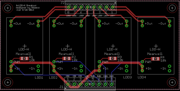
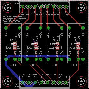
RRASCO-
I've had a few people asking me ( Via PM ) for a PcB with the "PullDown resistor" as an option. Here's what I came up with-
The PWM pins can be pulled low by installing a jumper, or left to open to " "float high".
If anyone else wants the Gerber files for this version, just let me know and I'll post'em up.
That's sweet. Though, it would add costs, while minimal, still an extra part to build. I say you post those files up. I will upgrade my board to include the pull-down resistors that way people can decide on which one they want. Options are good.
I've converted to using DIY controllers to make it cheaper. For a single use, the cost isn't much less, but once you have a PCB and the parts, it gets cheaper each time you need one. Which for me, is becoming quite often.
Amen to that! Even if you don't have a stand alone PcB, a small piece of proto-board will work in a pinch. You can build a dedicated controller for around $10 in parts Vs $29 for a full blown UNO.
rrasco
Active member
Updated both the LDD-Lx4 and LDD-Hx4 to v2.0 which includes the 1206 10k pull down resistor. Gerber files at Google Code below.
http://code.google.com/p/meanwell-ldd-led-driver/downloads/list
http://code.google.com/p/meanwell-ldd-led-driver/downloads/list
Attachments
Updated both the LDD-Lx4 and LDD-Hx4 to v2.0 which includes the 1206 10k pull down resistor. Gerber files at Google Code below.
http://code.google.com/p/meanwell-ldd-led-driver/downloads/list
Thanks! I appreciate the help. I will be ordering from ITead soon!
WOW this threads been busiy the last couple days!
")
Rott, any sort of 555 timer circuit will work. such as the cheap 3-4 dollar ones on ebay for manuall dimming of the LDD. you just have to hook them up properly. not using the v+ output connection......
This post a couple pages back makes me wonder. I thought the HLG was an LED Current driver? and couldn't be used to run the LDD's. or did I miss something here (goes out to the electical engineers among us) otherwise very neatly organized electronics, makes me thing this person knows what they are doing and I just missed something.Hi your set up looks great. I am doing more or less a similar set up. Can you please advise how you have connected Steve's interface to the drivers?
I beleive you can just ship them out as a "gift" and avoid any customs fees. (in our case this isn't really cheating the system as we aren't in this for profit.....I am in the same boat as well. I don't have a problem organizing a purchase for a bunch of boards. I am sure they will not ship to everyone individually, but I am fine with distributing them once I get them.
daplatapus - I can ship to you, but I'm not sure what the cost will be to get through customs.
is there an alternative way to dim the ldd1000 not using a arduino? I just need a cheap way to dim 10 3W leds all RB
Rott, any sort of 555 timer circuit will work. such as the cheap 3-4 dollar ones on ebay for manuall dimming of the LDD. you just have to hook them up properly. not using the v+ output connection......
daplatapus
New member
I beleive you can just ship them out as a "gift" and avoid any customs fees. (in our case this isn't really cheating the system as we aren't in this for profit.....
Sweet, than if someone is willing to do some legwork for me, I'm definitely in.
chicken
Premium Member
This post a couple pages back makes me wonder. I thought the HLG was an LED Current driver? and couldn't be used to run the LDD's. or did I miss something here (goes out to the electical engineers among us) otherwise very neatly organized electronics, makes me thing this person knows what they are doing and I just missed something.
The HLG's run as either constant current or constant voltage based on how you have the pots adjusted. I wanted a power supply that did not need a fan running to cool it as they always seem to die on me. I have all of my LEDs running right now except the TV's and HV's for the last 9 hours which is about 3.2 amps @ 54v DC and its running fairly warm at 130 degrees. It is not getting any airflow though as it is sitting under the tank enclosed in the cabinet. It will be interesting to see how much hotter it gets as I bring the rest of the LEDs online. My max string string is @ about 38v DC so with the LDD overhead I could dial down the voltage on the HLG to see if it helps with efficiency and heat. Its on my list to test and post the results. Otherwise so far its just worked.
gandalfdgrey
New member
Hi,
O2Surplus I am interested in your design. Can you please post the gerber files? Do you have a part number for a suitable jumper?
Thanks.
O2Surplus I am interested in your design. Can you please post the gerber files? Do you have a part number for a suitable jumper?
Thanks.
Updated both the LDD-Lx4 and LDD-Hx4 to v2.0 which includes the 1206 10k pull down resistor. Gerber files at Google Code below.
I'm no electronics genius, but if I follow what I've been reading, all this addition does is prevent the LEDs from baking in the event of a power failure when the unit comes back on, correct?
I ordered my 5 LDD boards earlier this evening before finishing the last few pages of the thread... doh!
Hi,
O2Surplus I am interested in your design. Can you please post the gerber files? Do you have a part number for a suitable jumper?
Thanks.
Here are the Gerber files for the PcB's to be made @ ITeadStudio. The jumpers are constructed using standard .1" pin headers. You'll find them anywhere computer parts are sold.
Jumper-http://www.digikey.com/product-detail/en/382811-8/A26228-ND/293121
Snap-able Pin Header-http://www.digikey.com/product-detail/en/PRPC040SAAN-RC/S1011EC-40-ND/2775214
Similar threads
- Replies
- 3
- Views
- 2K
- Replies
- 46
- Views
- 13K